Rotation of rigidbody composed of point masses - weird behaviour

Started by
3 comments, last by JoeJ 4 years ago

Hey,

I have a set of loose point masses. I integrate velocities like this:

for (int i = 0; i < pointMasses.Length; i++)
	pointMasses[i].velocity += pointMasses[i].force * dt / pointMasses[i].mass;

I thought about making an experiment. I took 4 points masses and positioned them such that they compose a box. I wanted to use rigidbody formulas to make the “rigidbody” rotate correctly, i.e. determine point masses's points such that after integration they still maintain distances between each other unchanged + angles.

The basic formula for velocity of a moving point (Q) relative to rigidbody's center of mass (P) is this:

Q_v = P_v + W x (Q - P)

Q_v - velocity of Q
P_v - linear velocity of rigidbody (or center of mass)
W - angular velocity of rigibody

Code (in C#) that does integration looks like this:

Inputs are:
- pointMasses - list of point masses
- force
- pointOfForceApplication - set to one of the pointMasses

========

float dt = Time.fixedDeltaTime;

Vector3 avgPos = [...];
Vector3 avgVel = [...];

Vector3 angMomentum = Vector3.zero;
Matrix4x4 inertia = Matrix4x4.identity;
{
	float xx = 0.0f;
	float yy = 0.0f;
	float zz = 0.0f;
	float xy = 0.0f;
	float xz = 0.0f;
	float yz = 0.0f;
	
	for (int i = 0; i < pointMasses.Length; i++)
	{
		float m = 1.0f;
		Vector3 r = pointMasses[i].position - avgPos;
		Vector3 v = pointMasses[i].velocity;

		angMomentum += Vector3.Cross(r, m * v);

		xx += (r.y * r.y + r.z * r.z) * m;
		yy += (r.x * r.x + r.z * r.z) * m;
		zz += (r.x * r.x + r.y * r.y) * m;
		xy += (r.x * r.y) * m;
		xz += (r.x * r.z) * m;
		yz += (r.y * r.z) * m;
	}
	
	inertia.m00 = xx;
	inertia.m01 = -xy;
	inertia.m02 = -xz;
	inertia.m10 = -xy;
	inertia.m11 = yy;
	inertia.m12 = -yz;
	inertia.m20 = -xz;
	inertia.m21 = -yz;
	inertia.m22 = zz;
	
	inertia = inertia.inverse;
}

// get new linear velocity
Vector3 linVel = avgVel + force * dt / 4.0f; // 4 point masses each with mass 1.0

// get new angular velocity
Vector3 pf = pointOfForceApplication - avgPos;
Vector3 torque = Vector3.Cross(pf, force);
Vector3 angAcc = inertia.MultiplyVector(torque);
Vector3 angVel = inertia.MultiplyVector(angMomentum);
angVel += angAcc * dt;

for (int i = 0; i < pointMasses.Length; i++)
{
    Vector3 r = pointMasses[i].position - avgPos;
    pointMasses[i].velocity = linVel + Vector3.Cross(angVel, r);
}

The problem

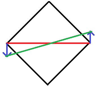
The problem that I have is that as the point masses set keeps rotating the object becomes “bigger”. I am using a simple 2D box (I am using full 3D formulas though) to keep things as simple as possible. I apply force to one of the vertices of the box.

Have a look at this screenshot:

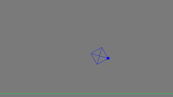
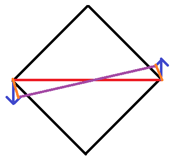
It shows the initial state. I apply force to the bolded point. After a few seconds of rotation (just angular velocity, I removed linear velocity to make the box stay in one place) this is what I get:

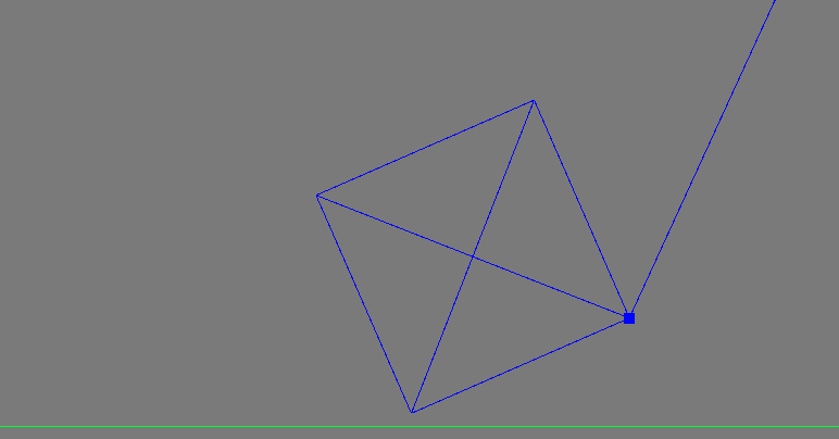
(The long line shows the direction of angular velocity of the bolded point).

Does anyone know why would the box grow bigger as it keeps rotating?

Advertisement

wojtsterna said:
Does anyone know why would the box grow bigger as it keeps rotating?

Because rotation is combination of two motions - one from the linear velocity of the particle (which is always a straight line), and second a force that tries to keep the point at a certain distance to some origin, or gravity for example (centripetal force).

Seems you miss the second one. Nothing stops the particles from keeping straight trajectory, so the distance from the origin increases and it looks like scaling.

Two options:

1. Particle simulation with constraints: Add some distance constraints, e.g. along the blue lines. (But the body will wobble a bit and may even flip over on some collision or other big external force.)

2. Rigid body simulation: Tries to model the behavior of rigid matter that can not change shape. (Which does not exist in reality, but is robust at keeping the shape.)

There seems a flaw in your code. I think you try to model inertia in global space. But this can only cause problems. Notice that the inertia matrix we often use can only represent ellipsoids, and is only an approximation of real world rigid body mass properties.
It depends on the alignment of the coordinate frame. So you should use a local frame of the body that represents its shape well.

The problem if doing it in global space is this:

If the rectangle rotates, mass properties oscillate from horizontal and vertical ellipses to a circle if the object is diagonal and badly aligned to global axis.

This is why rigid body simulators rotate the inertia matrix with the object, so the shape of the ellipse remains constant. If it oscillates, you will add energy to the system and the simulation becomes unstable and wrong.

With particle physics it is not necessary to model inertia because it is just a result of constrained point masses, just like rotation is.

I had a bit of time to think about your answer @joej ?.

and second a force that tries to keep the point at a certain distance to some origin, or gravity for example (centripetal force).

Seems you miss the second one

In general, yes. When I am trying to model a rigidbody using a set of particles I'd need to have that force that keeps particles apart at certain distance. However, note that I am actually modelling the rigidbody with rigidbody equations. The particles are just there so that I could draw the outline of the rigidbody. I model the rigidbody and then, using rigidbody equation for a velocity of a point, I apply that formula to all particles.

I think I now why the object becomes bigger. Have a look at this picture:

We have a box/square in initial position. Then I apply a force to the body which will make it rotate. The vertices on the left and right have their velocity vectors (blue) calculated. The red line is the initial distance between them. Now, when I move those vertices in the integration step, their distance will now be the green line, which is bigger than the red one. With each such integration step the distances between vertices grow and grow. This also explains why, when I rotate the square faster, it grows bigger faster.

Let's say I accept this fact. So, the solution would be to somehow make the green line be as long as the red one after the integration. So I went through the trouble and implemented this (http://www.cs.uu.nl/docs/vakken/mgp/2016-2017/Lecture%207%20-%20Position-based%20Dynamics.pdf)​.Every bit of it (except for step (16) in section 3.1 which I do not need right now as it's for collisions). So now the distances between vertices do indeed hold (after constraints projection) but I have another problem - for some reason angular momentum is not preserved, even though the authors of the paper say it should be with the given constraints. Have a look at this picture:

The purple line is the new line that connects the left and right vertices, after integration and projection. However, due to how velocities are updated in step (13) (section 3.1 of the article), the new velocities will be the orange ones. And after projection they will be shorter than the original blue ones. This means loss of angular velocity for all vertices with each integration/projection step, what simply means that speed with which the square is rotating is slowing down with every frame.

I managed to “hack around” this problem by storing angular momentum of the rigidbody, and if in a given frame no forces act on the rigidbody, instead of calculating the angular momentum from the vertices (as is shown in section 3.5 of the article) I use that cache angular momentum. This works but I can't rid off of this feeling that this is a hack that should not be needed. The authors don't mention anything like that as well. So what could I be doing wrong? Can I somehow make sure that angular momentum is not changed after integration/projection?

wojtsterna said:
and then, using rigidbody equation for a velocity of a point, I apply that formula to all particles.

Yeah, and at this point you ‘miss’ the rigid body constraint that turns straight trajectories from linear velocity into a arc. So what you found out is the same thing i tried to say.

There is no need to differ between particle and rigid body simulation approaches - both try to model the same real world physics. But rigid body approach solves exactly your observed problem by introducing angular velocity and rotation. Instead considering individual point masses and constraints between them to preserve their shape, we model any rigid shape by precalculating its mass properties (mass, center of mass, moment of inertia). Integration considers only those properties, and the positions of individual particles can then be calculated simply from center of mass and orientation.

wojtsterna said:
I managed to “hack around” this problem by storing angular momentum of the rigidbody, and if in a given frame no forces act on the rigidbody, instead of calculating the angular momentum from the vertices (as is shown in section 3.5 of the article) I use that cache angular momentum.

What you do is a hacky way to calculate center of mass from all particles, and guessing orientation of the body so you can apply corrections.
The problem is your corrections probably do not obey the laws of physics. You add energy to the system and momentum is not preserved. After you add more bodies and let them interact, the simulation will jitter and will not converge and come to rest.

What you have is already a complex system of 4 particles that interact with each other. So you can solve it either by solving all constraints between those particles (option 1 from my first reply),
or by taking the shortcut of saying this body is stiff and it's shape will never change - so it becomes possible to make this rigid body abstraction most physics engines use (option 2).

wojtsterna said:
Can I somehow make sure that angular momentum is not changed after integration/projection?

Yes. It would be an option between the two i have mentioned. For example, you can sum up linear and angular momentum after your corrections, and then apply translation and rotation to the whole system so the net change becomes zero.
I did this, but it suffers from the fact this solution is limited to single bodies - we could simulate multiple such rectangles this way, but we still lack to model interaction between them (e.g. collision or resting contact), so we still need a system to model global constraints and to solve them.
Personally i ended up with particles that also had orientation so i could model more complex constraints like ragdoll joint limits. But i had no moment of inertia - instead i got the same realistic behavior by connecting two particles with a distance constraint so it forms a capsule which shape i also used for collisions.
So i had a physics engine that was between the two primary options, which seems the same direction you are heading. It was not bad but i gave up on it when Havok became free, and nowadays we have many options of good free physics engines. I would still use my system for simple effects like foliage reacting to player, eventually.

So, everything is possible. It is just hard to figure out how to do it correctly. And whatever options you choose and combine, the core problem of solving many constraints can not be avoided. (My motivation was to keep things ‘simpler’, but it did not really work out ; )

This topic is closed to new replies.

Advertisement