The planned specs are (as a starting point):
- 10 MHz Z80180 CPU;
- 64KB RAM (2 32Kx8 SRAM chips);
- 128KB Flash ROM;
- Graphical LCD;
- Simple joypad input;
- Keyboard input (AT using either software AT routines or dedicated microcontroller).
In the meantime, I've concentrated on the graphical LCD. I picked a 128x64 backlit graphical LCD for the princely sum of GBP16. It's very easy to control - you hook up it up to a 8-bit data bus to transfer image data and instructions and a handful of control pins to indicate what you're doing on that bus (reading or writing, whether you're sending an instruction or some image data, that sort of thing) and that's it - the only supporting circuitry it requires is a 10K potentiometer to act as a contrast control and power for the display and backlight.
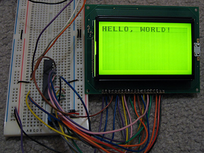
To experiment with the LCD, I'm using a PICAXE-28X1 microcontroller, programmed in BASIC. There isn't much space to store graphics, so I'm using a 32 character font (at eight bytes per character, that takes up all 256 bytes of free EEPROM space!)
; LCD data bus should be connected to port C.Symbol LcdRegisterSelection = 0 ; D/I : 4Symbol LcdReadWrite = 1 ; R/W : 5Symbol LcdStartEnable = 2 ; E : 6Symbol LcdChipSelect1 = 3 ; CS1 : 15Symbol LcdChipSelect2 = 4 ; CS2 : 16Symbol LcdReset = 5 ; /RST : 17; Storage for console state variables.Symbol ConsoleX = B10Symbol ConsoleY = B11Symbol ConsoleChar = B12 GoSub LcdInit ; Initialise LCD. B0 = %00111111 : GoSub LcdWriteInstruction ; Switch LCD on. GoSub LcdClear ; Clear LCD ; Write the obligatory message to the LCD. ConsoleX = 0 : ConsoleY = 0 ConsoleChar = $08 : GoSub LcdPutChar ; H ConsoleChar = $05 : GoSub LcdPutChar ; E ConsoleChar = $0C : GoSub LcdPutChar ; L ConsoleChar = $0C : GoSub LcdPutChar ; L ConsoleChar = $0F : GoSub LcdPutChar ; O ConsoleChar = $1D : GoSub LcdPutChar ; , ConsoleChar = $00 : GoSub LcdPutChar ; ConsoleChar = $17 : GoSub LcdPutChar ; W ConsoleChar = $0F : GoSub LcdPutChar ; O ConsoleChar = $12 : GoSub LcdPutChar ; R ConsoleChar = $0C : GoSub LcdPutChar ; L ConsoleChar = $04 : GoSub LcdPutChar ; D ConsoleChar = $1B : GoSub LcdPutChar ; ! Pause 2000 B2 = 0 MainLoop: B2 = B2 - 1 B0 = B2 GoSub LcdGotoZ Pause 30 GoTo MainLoopLcdInit: DirsC = $00 ; Set data bus to input. High LcdStartEnable ; We're not writing anything. High LcdChipSelect1 High LcdChipSelect2 Low LcdReset Pause 500 High LcdReset Pause 500 ReturnLcdWriteInstruction: Low LcdReadWrite DirsC = $FF ; Data bus = output. PinsC = B0 ; Set data bus state. Low LcdRegisterSelection ; Instruction, not data. Low LcdStartEnable High LcdStartEnable DirsC = $00 ; Leave data bus floating. ReturnLcdWriteData: Low LcdReadWrite DirsC = $FF ; Data bus = output. PinsC = B0 ; Set data bus state. High LcdRegisterSelection ; Data, not instruction. Low LcdStartEnable High LcdStartEnable DirsC = $00 ; Leave data bus floating. ReturnLcdGotoX: B0 = B0 And 7 B0 = B0 + %10111000 GoTo LcdWriteInstruction LcdGotoY: B0 = B0 And 63 B0 = B0 + %01000000 GoTo LcdWriteInstructionLcdGotoZ: B0 = B0 And 63 B0 = B0 + %11000000 GoTo LcdWriteInstructionLcdClear: For B2 = 0 To 7 B0 = B2 GoSub LcdGotoX B0 = 0 GoSub LcdGotoY B0 = 0 For B3 = 0 To 63 GoSub LcdWriteData Next Next B2 ReturnLcdPutMap: B1 = B0 * 8 For B2 = 0 To 7 Read B1, B0 GoSub LcdWriteData B1 = B1 + 1 Next B2 ReturnLcdPutChar: B0 = ConsoleY GoSub LcdGotoX B0 = ConsoleX * 8 If B0 < 64 Then Low LcdChipSelect2 Else Low LcdChipSelect1 B0 = B0 - 64 EndIf GoSub LcdGotoY B0 = ConsoleChar GoSub LcdPutMap High LcdChipSelect1 High LcdChipSelect2 ConsoleX = ConsoleX + 1 If ConsoleX = 16 Then ConsoleX = 0 ConsoleY = ConsoleY + 1 If ConsoleY = 8 Then ConsoleY = 0 EndIf EndIf Return ; FontEEPROM $00,($00,$00,$00,$00,$00,$00,$00,$00,$7E,$7F,$09,$09,$7F,$7E,$00,$00)EEPROM $10,($7F,$7F,$49,$49,$7F,$36,$00,$00,$3E,$7F,$41,$41,$63,$22,$00,$00)EEPROM $20,($7F,$7F,$41,$63,$3E,$1C,$00,$00,$7F,$7F,$49,$49,$49,$41,$00,$00)EEPROM $30,($7F,$7F,$09,$09,$09,$01,$00,$00,$3E,$7F,$41,$49,$7B,$3A,$00,$00)EEPROM $40,($7F,$7F,$08,$08,$7F,$7F,$00,$00,$41,$41,$7F,$7F,$41,$41,$00,$00)EEPROM $50,($20,$61,$41,$7F,$3F,$01,$00,$00,$7F,$7F,$1C,$36,$63,$41,$00,$00)EEPROM $60,($7F,$7F,$40,$40,$40,$40,$00,$00,$7F,$7F,$06,$1C,$06,$7F,$7F,$00)EEPROM $70,($7F,$7F,$0C,$18,$7F,$7F,$00,$00,$3E,$7F,$41,$41,$7F,$3E,$00,$00)EEPROM $80,($7F,$7F,$09,$09,$0F,$06,$00,$00,$3E,$7F,$41,$31,$6F,$5E,$00,$00)EEPROM $90,($7F,$7F,$09,$19,$7F,$66,$00,$00,$26,$6F,$49,$49,$7B,$32,$00,$00)EEPROM $A0,($01,$01,$7F,$7F,$01,$01,$00,$00,$3F,$7F,$40,$40,$7F,$3F,$00,$00)EEPROM $B0,($1F,$3F,$60,$60,$3F,$1F,$00,$00,$7F,$7F,$30,$1C,$30,$7F,$7F,$00)EEPROM $C0,($63,$77,$1C,$1C,$77,$63,$00,$00,$07,$0F,$78,$78,$0F,$07,$00,$00)EEPROM $D0,($61,$71,$59,$4D,$47,$43,$00,$00,$00,$00,$5F,$5F,$00,$00,$00,$00)EEPROM $E0,($02,$03,$59,$5D,$07,$02,$00,$00,$00,$80,$E0,$60,$00,$00,$00,$00)EEPROM $F0,($00,$00,$60,$60,$00,$00,$00,$00,$07,$07,$00,$07,$07,$00,$00,$00)The code isn't very robust - it doesn't check the state of the LCD's busy flag as I'm assuming that a 4MHz PIC running an interpreted BASIC is too slow to manage to write another byte to the LCD driver before it has finished processing the last one.
The font was generated from the following image (it's the BBC Micro font):
It's rotated through 90? as, unlike the LCD driver in the TI-83+, each byte written outputs 8 pixels vertically, with the least significant at the top. (On the TI-83+, each byte written outputs 8 pixels horizontally, with the most significant bit on the left). More interestingly, this graphical LCD is made up of two 64x64 regions next to eachother, and by controlling two chip select pins you can control whether each byte written updates the left side, the right side, neither or both. I'm entirely sure how I could use this, though, other than not-very-exciting tricks like clearing the LCD extra-fast.
924KB WMV
Finally, here's a video of the LCD test in action. It's not very speedy, but will hopefully pick up some speed once I figure out how I'm going to use that Z80180 CPU. [smile]