Isometric view with 2 grids & tile size

Started by
18 comments, last by Scouting Ninja 5 years, 10 months ago

Hello,

I'm not sure if my approach of an isometric grid for a mobile game, is a good one.
Please have a look at the image.

The 100x100 grid is just for positioning the images on the grid. The background comes from the base tile and is one image and comes in different resolutions for different screen densities.

Is this even possible or a performance killer?

Also, I choosed 1 unit = 1 meter sidelength for a tile in worldspace, because I'm modeling the buildings in Blender also with a 1m reference object, to get a better sense of the dimension they would take in worldspace.


Your thoughts about it?


Thanks in advance!


Additional information:
I'm using libgdx and the default y/x plane is transformed by a transformation matrix to z/x plane. Don't know if this is common, but a blogpost (https://www.badlogicgames.com/wordpress/?p=2032) did so.

ctile_frage.png

Advertisement

Okay, so it seems that I do not understand some tricks, how images work an isometric grid.

If you have a look at
ip2_tiles.jpg.ce54f382471c7306de546dc30ff40a8b.jpg
of a finished game, it looks like there are no image tiles for the buildings. Instead, fully 2d images applied on a predefined gridspace at once.The windmill occupies 2x2 gridspace (red lines), but needs much more tiles to display the image? (blue lines)
In the violet circle, the building takes a 3x3 space on the grid. Is the image composed of tiles or one single image? Last guess I would have are 3d objects.

If I'm drawing an image
b.png.f6d7da205cd988ce90e08760d744df41.png
at my grid, it looks like
b_on_grid.jpg.da09ca085cf3faa40c9d2dc7a18af956.jpg
But it should be drawn like
b_on_grid.jpg.c20c5afc21bbc8258df37e6212f5f1e9.jpg
Is this a camera issue or am I just to stupid to understand something major about isometric perspective?

Or has this something to do with the source image? All isometric graphics I found on the net of buildings, trees, and so on, are square images and already in isometric perspective, like the gray box. Some are a set to compose a building like seen here https://en.wikipedia.org/wiki/File:Tile_set.png, but the composed ones of that tiles doesn't look as good as for an example, an image like this one (from a 3D game)
jpe.jpg.cc9923c5d08ba3f8b1746503410c145e.jpg
That's what I'm trying to achieve. Bake a 2d image in isometric perspective in Blender of a building like that, and get it on the grid as a whole, occupying gridspace depends on the size of the building.

Not possible?

I have been work the same things recently and hope I can shed some light.


A) The windmill consist of more than 2x2 tiles indeed, it´s because it has an unnormal height. Unnormal heights are the meaning that the building or object is taller than what one tile can render. To do this, you use the same x&y grid coordinate but you take account for the height, which is calculated by adding ( or removing ) extra values to Y. If you take your isometric cube in photoshop and try to make it taller by adding more cubes on top, how would you do it then? The same principle applies in the game as well. 
 

B ) Your cube looks like that because you are putting a plane on the terrain. You should just render it as a quad facing the camera. And use the tile positioning system. this way it will be a camera facing quad like in photoshop and thus display the image correctly as your artist will make it according to a front facing quad.

In my solution, I render the terrain as quads facing the camera but using the isometric grid math to get the correct positioning. I use the same formula to render my objects as well.

"There will be major features. none to be thought of yet"

Thanks. I thought of something like this, but had doubts, how things later behave, when I want to select a building to interact with. But with an invisible isometric grid as kind of a logic grid, I can just check which tile is clicked and the building, who occupies it.

I like your approach of simplicity.
What I currently have, is an orthographic camera looking with direction vector (-1,-1,-1) to the origin.
A transform matrix rotates the default Y-X-Plane to Z-X by 90° around the x-axis.
So I'm not sure, if it's a good solution, to give each image of a building a transform matrix as well, to face the camera.
This seems too much, compared to your solution just working on the Y-X.
Do I complicating things?
Even though, I can't figure out the right rotation vector to face the camera as square.
proj.png.4d779bb976ed1f5d95add0ead326dd55.png
Maybe I should refresh some math?
With


final Matrix4 imageFaceCameraMatrix = new Matrix4();

imageFaceCameraMatrix.setToRotation(new Vector3(0, 1f, 0), 45);

I'll get the following (not square)
proj2.png.5fdad1019ee49b0ffe81f6fa04fca518.png
I tried chaining the 2 matrices, with no success. Just discovered the multiplication methods of the Matrix4 class. Maybe there is the key to a solution.


Your second picture looks like the correct output. And using matrixes for this is fine. However, i would build the system so that the camera facing quads already have a precalculated vertex buffer so it faces the camera. that way you dont need any matrix multiplication on the cpu/gpu. You can just add the position to the vertex buffer and get the desired location.

For your second picture, if you move that quad somewhere over the tile grid you will see that it matches but you have scewd outlines in the texture itself, this is no hard problem becuase you can change the texture to match pixel perfect. 
 

Im also not sure now what you exactly see as the problem since the second picture does get you the right output.

"There will be major features. none to be thought of yet"

Hello and thank you.
Had to look up, what a vertex buffer is and what it does.
I'm guessing an image is like a plane, defined by 4 vertices?
I will build that system what you suggested. It's far easier than my approach. Just want to know, how the square result would be possible with the actual system.

As you mentioned, it looks scewed. But it's the same square image I posted in my second post. So I thought I need to find a vector that displays it and all other images square to the cam.
the_vector.png.1a7339cb283626e27b6a62d5c305cb0b.png

1 hour ago, Androphin said:

I'm guessing an image is like a plane, defined by 4 vertices?

Yes, that way you can edit the matrix to move, rotate and scale an object.

With 2D games you only need to adjust the matrix to match the viewport; the art is design isometric from the start. So a 2D isometric image often acts like particles in games. With the images pointing at the camera:

IsoImage.thumb.jpg.cd4113110a9f3b15f61649a1d6c5c2e0.jpg

I made this image in Blender to demonstrate, as you can see it looks at the camera and you only scale their matrix when you want want it to fit the viewport.

On 6/13/2018 at 11:43 AM, Androphin said:

Is this even possible or a performance killer?

Looking at your planned workflow, nothing is a performance killer there. You will need to batch images at least, some dynamic batching would be perfect.

Overdraw will be a thing with your layer system but can be avoided if you use a grid system. Although with only 3 layers, it will be a minor problem for you.

That's exactly the problem I have with my dummy image. I don't know how to adjust the image's matrix to the viewport's one.
view.thumb.png.41ff78e109ccb3bd39a01c3823b08b65.png

27 minutes ago, Androphin said:

I don't know how to adjust the image's matrix to the viewport's one.

The cube image you are using there, isn't a isometric image; so using it to test your view won't help much. Instead render a cube from a 45 degree angle in Blender; using the orthographic camera.


If you are using a orthographic camera, you don't need to scale the image. So often it's better to just use a orthographic camera from the start. Else you need to project each sprite on their own.

https://github.com/libgdx/libgdx/wiki/Projection,-viewport,-&-camera

Video: https://www.youtube.com/watch?v=mLbbcoLHKqY

Edit: Video and wiki aren't the same; I just added the video, if the wiki doesn't make sense.


Setting up a orthographic camera is easy. This way you don't need to project each and every matrix each time, the camera will adjust the image when you render,

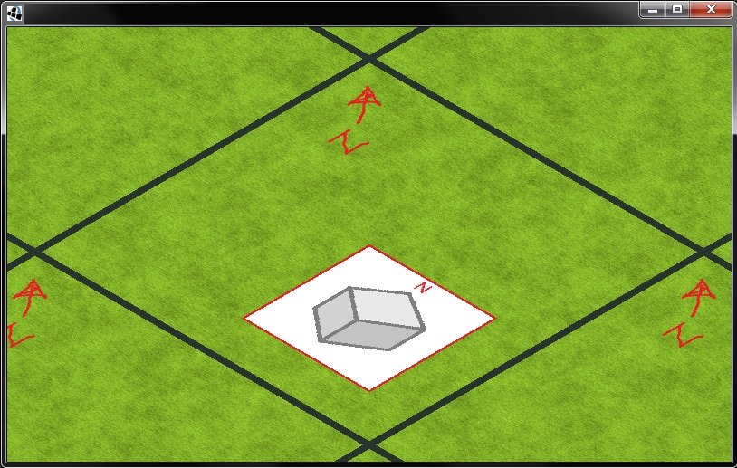
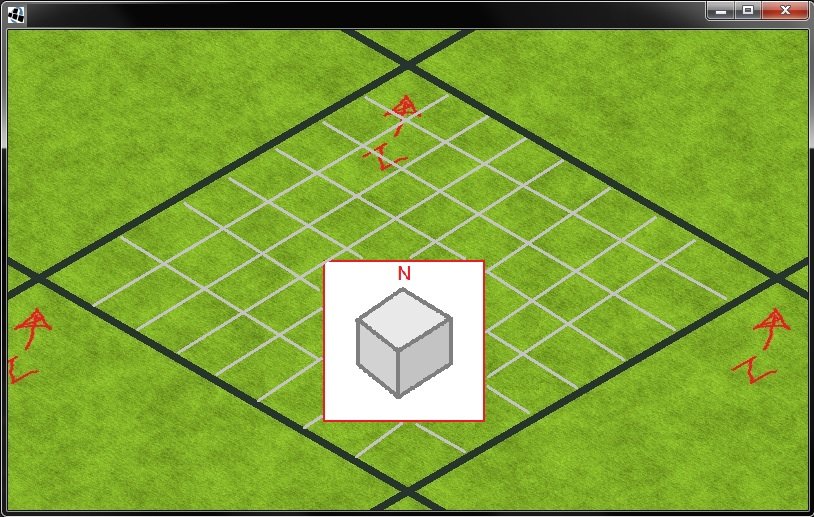
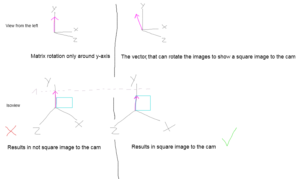
I'm using an orthographic camera. Due to the direction and position of the cam, I needed a rotation-matrix for the isometric perspective. (As described in my 3rd post)
But the image is drawn at the default y/x, because I don't apply the rotation-matrix on it.
The spritebatch's projection matrix is set to the orthographic camera's combined one.

Source code:


package com.androtest.iso;

import com.badlogic.gdx.ApplicationAdapter;
import com.badlogic.gdx.Gdx;
import com.badlogic.gdx.InputAdapter;
import com.badlogic.gdx.graphics.*;
import com.badlogic.gdx.graphics.g2d.Sprite;
import com.badlogic.gdx.graphics.g2d.SpriteBatch;
import com.badlogic.gdx.graphics.g2d.SpriteCache;
import com.badlogic.gdx.graphics.glutils.ShapeRenderer;
import com.badlogic.gdx.math.Intersector;
import com.badlogic.gdx.math.Matrix4;
import com.badlogic.gdx.math.Plane;
import com.badlogic.gdx.math.Vector3;
import com.badlogic.gdx.math.collision.Ray;

public class Init extends ApplicationAdapter {

   public static final int SCREEN_WIDTH = 800;
   public static final int SCREEN_HEIGHT = 480;

   int WORLD_WIDTH = 200;
   int WORLD_HEIGHT = 200;
   float screenAspectRatio;

   Texture terrain;
   Texture squareDummy;
   Texture tex;
   SpriteBatch batch;


   public class OrthoCamController extends InputAdapter {
      final OrthographicCamera camera;
      final Plane xzPlane = new Plane(new Vector3(0, 1, 0), 0);
      final Vector3 intersection = new Vector3();
      Sprite lastSelectedTile = null;
      int zoomLevel = 0;

      public OrthoCamController (OrthographicCamera camera) {
         this.camera = camera;
      }
      final Vector3 curr = new Vector3();
      final Vector3 last = new Vector3(-1, -1, -1);
      final Vector3 delta = new Vector3();
      @Override public boolean touchDragged (int x, int y, int pointer) {
         Ray pickRay = camOrtho.getPickRay(x, y);
         Intersector.intersectRayPlane(pickRay, xzPlane, curr);

         if( !(last.x == -1 && last.y == -1 && last.z == -1) ) {
            pickRay = camOrtho.getPickRay(last.x, last.y);
            Intersector.intersectRayPlane(pickRay, xzPlane, delta);
            delta.sub(curr);
            camOrtho.position.add(delta.x, delta.y, delta.z);
         }
         last.set(x, y, 0);
         return false;
      }

      @Override public boolean touchUp(int x, int y, int pointer, int button) {
         last.set(-1, -1, -1);
         return false;
      }
   }
   OrthographicCamera camOrtho;
   OrthoCamController ctrl;
   final Sprite[][] sprites = new Sprite[3][3];
   final Matrix4 XYtoXZmatrix = new Matrix4();
   final Matrix4 imageFaceCameraMatrix = new Matrix4();

   ShapeRenderer sr;

   static final int LAYERS = 1;
   static final int TILES_X = 20;
   static final int TILES_Z = 20;
   static final int TILE_WIDTH = 30;
   static final int TILE_HEIGHT = 30;
   static final int TILE_HEIGHT_DIAMOND = 28;

   SpriteCache[] caches = new SpriteCache[LAYERS];
   int[] layers = new int[LAYERS];

   @Override
   public void create(){
      terrain = new Texture(Gdx.files.internal("tile_grass.png"));
      squareDummy = new Texture(Gdx.files.internal("b2.png"));
      Pixmap pxm = new Pixmap(2,2, Pixmap.Format.RGBA8888);
      pxm.setColor(0f, 0.5f, 1f, 0.2f);
      pxm.fill();
      tex = new Texture(pxm);

      batch = new SpriteBatch();

      camOrtho = new OrthographicCamera(WORLD_WIDTH, WORLD_HEIGHT*(Gdx.graphics.getWidth()/Gdx.graphics.getHeight()) );
      camOrtho.position.set(WORLD_WIDTH*2, WORLD_HEIGHT, WORLD_WIDTH*2);
      camOrtho.direction.set(-1,-1,-1);
      camOrtho.near = 1;
      camOrtho.far = 10000;
      camOrtho.update();

      ctrl = new OrthoCamController(camOrtho);
      Gdx.input.setInputProcessor(ctrl);

      XYtoXZmatrix.setToRotation(new Vector3(1,0,0), 90);

      //imageFaceCameraMatrix.setToRotation(new Vector3(0, 1f, 0), 45);
      //imageFaceCameraMatrix.setToRotation(new Vector3(1f, 0f, -1f), -45);
      //imageFaceCameraMatrix.setToRotation(new Vector3(1f, 0f, 1f), 30);
      imageFaceCameraMatrix.setToLookAt(new Vector3(1f,1f,1f), new Vector3(0,1,0));


      sr = new ShapeRenderer();

      for(int z = 0; z < 3; z++) {
         for(int x = 0; x < 3; x++) {
            sprites[x][z] = new Sprite(terrain);
            sprites[x][z].setPosition(x,z);
            sprites[x][z].setSize(TILE_WIDTH, TILE_HEIGHT);
            sprites[x][z].flip(false, true);
         }
      }

      for (int i = 0; i < LAYERS; i++) {
         caches[i] = new SpriteCache();
         SpriteCache cache = caches[i];
         cache.beginCache();

         int colX = 0;
         int colZ = 0;
         for (int x = 0; x < TILES_X; x++) {
            for (int z = 0; z < TILES_Z; z++) {
               int tileX = colX + x*TILE_WIDTH;
               int tileZ = colZ + z*TILE_HEIGHT;
               cache.add(tex, tileX*1.1f, tileZ*1.1f, 0, 0, TILE_WIDTH, TILE_HEIGHT);
            }
         }

         layers[i] = cache.endCache();
      }
   }

   @Override
   public void render() {
      Gdx.gl.glClearColor( 0.154f, 0.200f, 0.184f, 1f );
      Gdx.gl.glClear(GL20.GL_COLOR_BUFFER_BIT | GL20.GL_DEPTH_BUFFER_BIT );
      Gdx.gl.glEnable(GL20.GL_BLEND);
      Gdx.gl.glBlendFunc(GL20.GL_SRC_ALPHA, GL20.GL_ONE_MINUS_SRC_ALPHA);

      camOrtho.update();

      for (int i = 0; i < LAYERS; i++) {
         SpriteCache cache = caches[i];
         cache.setProjectionMatrix(camOrtho.combined);
         cache.setTransformMatrix(XYtoXZmatrix);
         cache.begin();
         cache.draw(layers[i]);
         cache.end();
      }

      batch.setProjectionMatrix(camOrtho.combined);
      batch.setTransformMatrix(imageFaceCameraMatrix);
      batch.begin();
      batch.draw(squareDummy, 0, 0);
      batch.end();

      sr.setProjectionMatrix(camOrtho.combined);
      sr.setTransformMatrix(XYtoXZmatrix);
      sr.begin(ShapeRenderer.ShapeType.Line);
      sr.setColor(1, 1, 1, 1);
      sr.line(0, 0, 500, 0);
      sr.line(0, 0, 0, 500);

      sr.setTransformMatrix(new Matrix4().setToRotation(new Vector3(1,0,0),0));
      //x
      sr.setColor(Color.RED);
      sr.line(0,0,0, 500,0,0);
      //y
      sr.setColor(Color.GREEN);
      sr.line(0,0,0, 0,500,0);
      //z
      sr.setColor(Color.BLUE);
      sr.line(0,0,0, 0,0,500);

      sr.end();
   }

   @Override
   public void resize(int width, int height) {
      camOrtho.viewportWidth = width;
      camOrtho.viewportHeight = height;
      camOrtho.update();
   }

   @Override
   public void dispose() {
      terrain.dispose();
      building.dispose();
      tex.dispose();
      batch.dispose();
      sr.dispose();
   }
}


This topic is closed to new replies.

Advertisement