Mesh simplification algorithms have been around for a while now. Most of the public code seems to be variations on quadric mesh simplification. An example is https://github.com/sp4cerat/Fast-Quadric-Mesh-Simplification That approach works well for watertight volumes with no thin parts, but is terrible for thin sections such as clothing and wings. Here's why.
Quadric mesh simplification is trying to minimize the error volume between the original mesh and the reduced mesh. Trimming the edges of a thin part doesn't change the volume much. So a quadric mesh optimizer will tend to trim the edges of thin areas. This looks awful on certain types of models.
So, the big players, such as Unreal, go beyond that. Unreal's mesh simplifier has “silhouette protection”. This insures that the outline of the object won't change much. How do they do that? Is there code available?
It's all in the cost/error function you choose to use.
I've seen something akin to “Silhouette Protection” implemented by looking at surface area of the finished mesh, which can be done fairly quickly, and heard of but never seen options that would render silhouettes from a number of angles, and score before/after on how many pixels changed based on reduction, which sounds to me like a batch-like offline process.
How does Unreal specifically do it? I don't know! The code is gettable from git if you sign up for a free Unreal developer account, so you could perhaps look it up yourself?
Meshoptimizer has recently been tried by one of the Second Life devs.
That's what's not working. See this discussion where someone just tried it.
Mesh reduction test
Left to right:
High LoD model (1282 tris)
Optimized (manual) mid LoD model (480 tris)
GLOD mid LoD strenghtened (640 tris)
GLOD mid LoD default (320 tris)
MeshOptimizer mid LoD default (428 tris)
MeshOptimizer low LoD default (142 tris)
MeshOptimizer lowest LoD default (20 tris)
It's the last two on the right that need silhouette protection. If something is way off in the distance, you can lose the surface detail and the texture detail and no one will notice. Especially if you blur a little. But lose the outline, and it looks very wrong gets noticed as a defect. If it reduced all the way to a cube of the correct outline, that would be better than trimming the edges badly.
This is a consequence of using quadric mesh simplification on a thin surface such as the vase above, which is hollow. The criterion quadric mesh simplification uses is to minimize the error volume between the original and reduced mesh. This is a good criterion until it breaks the outline, as seen here.
Thus the need for silhouette protection, which I have not seen in any free code.
Silhouette features exist only in combination to an individual view of an observer, so it will be hard to relate this to features of a mesh. So that sounds useful only for distant objects which are seen from constant perspective, like the ridge of mountains in the far distance. But won't work for a vase on a table which you can see from all angles, which is your goal i guess. Maybe this makes ‘silhouette protection’ a bad search term. Afaik UE5 uses quadric error metrics as well and it looks like that, but i did not look into it.
Looking at the vase example gives me this idea, to prevent the collapsing of the opening on the top: Calculate the line field of primary curvature directions. The magnitude of those lines is high at the opening and at the base, where features are sharp and should be preserved. The direction of the lines allows to model some anisotropic objective, so reduction can still happen along the curvature, but not perpendicular to it, for example. (I could post an image to show how such line field looks like if you don't know about it.)
Nagle said: That approach works well for watertight volumes with no thin parts
Maybe that's specific to the implementation you linked at, which differs from the original paper because it clusters priority for speed and does not do it individually per edge. The original paper showed ability to merge close parts of different meshes, and also open meshes worked. So it should be quite flexible, but ofc. any reduction algorithm will generate bad results in cases.
JoeJ said: Silhouette features exist only in combination to an individual view of an observer, so it will be hard to relate this to features of a mesh.
Yes. Which is why I wonder how UE4 does it.
I'd thought about this before, in terms of picking some vertices which must not be deleted because they're on the “outer edge". That's hard to define. “Silhouette” is a bit better defined. One way to do that would be to project the mesh onto various view planes. The six planes of a cube, or the eight of an octahedron, perhaps. Then mark all the “outside” points, and make a perimeter. Then discard some of those that are too close together. (A high-rez sphere, for example, would result in circles with large numbers of points. That needs a 2D reduction to, say, a hexagon.)
Those silhouette points are then excluded from quartic mesh reduction.
That's kind of the big-hammer way to do it.
Silhouette protection sort of leads to impostor generation. If you mesh reduce as far as you can with silhouette protection, you get an object with very few vertices but roughly the same outline as the original. On that object you then paste the original textures. That's essentially an impostor. So there's potentially a smooth transition from mesh model to impostor.
Shame on Meshoptimizer. Maybe a path forward would be to crack open the code and start adding protection terms to the scoring algorithm it uses?
What you want is fundamentally not a well-behaved real-time process, though. The reason being that a vertex that's totally reducible when looking from one direction, is likely to be on the silhouette from another direction.
If you can find a proxy for “more drastic on the silhouette” then you could add that to the error metric in an existing algorithm. One proxy I can think of would be lost surface area when removing the vertex. Another would be lost edge loop length, although because the number of triangles changes, this ends up being tricky to calculate, as you'd need to identify which edges “matter more,” which is an authoring question, not an automatic question. Or, to put it another way: One formulation of what you're looking for might be exactly this: How to automate identifying interesting edge loops in the mesh!
Work I've seen in the past that might be related would come up with keywords like “feature preserving” or “bounded normal change.” Also, something something Hausdorff Distance?
There's so damned many of these schemes. Just check out kesen.realtimerendering.com and look at the siggraph lists especially for a neverending stream of paper going back forever.
Nagle said: I'd thought about this before, in terms of picking some vertices which must not be deleted because they're on the “outer edge". That's hard to define. “Silhouette” is a bit better defined. One way to do that would be to project the mesh onto various view planes. The six planes of a cube, or the eight of an octahedron, perhaps. Then mark all the “outside” points, and make a perimeter. Then discard some of those that are too close together. (A high-rez sphere, for example, would result in circles with large numbers of points. That needs a 2D reduction to, say, a hexagon.)
hmm… interesting. I image this algorithm: Instead cubemaps or rasterization, generate random plane directions, and increase the energy of each edge which has neighboring face normals pointing in opposite directions if dotted with the plane direction. Simple to implement and fast, but it has no occlusion which might be good or bad. Then, after thousands of iterations, what kind of energy would we see on the surface? In case of a sphere, each edge would have the same energy, but i fail to image what we get for a highly tessellated cube?
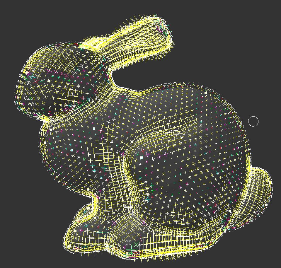
I assume it's not that great if your goal is triangle reduction. Because the result can be seen from every angle, it makes more sense to analyze the surface itself for important features. So i'll explain how this works with curvature directions for example. I found this screenshot, but it shows a crossfield, not a linefield:
You see the crosses have larger magnitude where curvature is high. High curvature means important features we want to keep. If it were a linefield instead crosses, the lines would be aligned with the flow of feature edges. Along this direction we can still use low mesh resolution, but perpendicular to it we want high resolution to capture the feature.
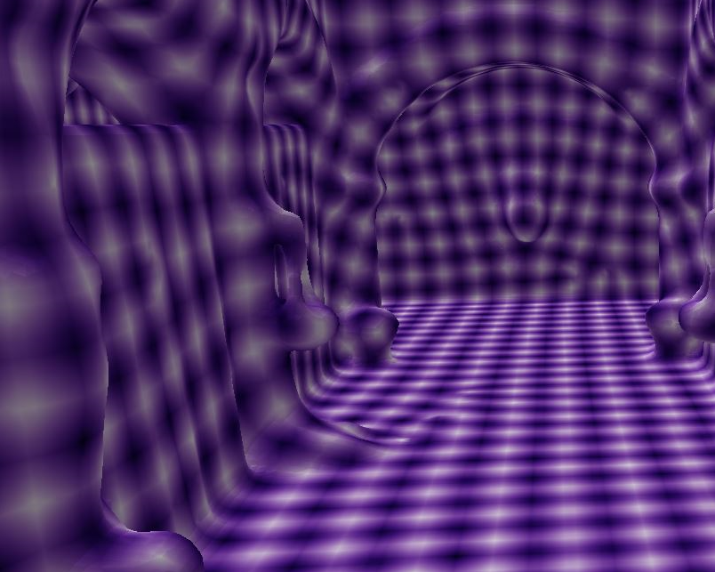
To know which vertices to keep, we can solve for a wavefield aligned with curvature directions:
My goal here is to have equally sized quads, but you can also set the wavelength to the desired resolution we have calculated from the first step. The reduction process can then be driven from the amplitude of the wave.
However, such algorithms are usually used for remeshing, not for reduction. And they require good meshes as input and are harder to implement than a queue of edge collapses using a simple metric. But maybe it's some inspiration to improve the metric.
Nagle said: Silhouette protection sort of leads to impostor generation. If you mesh reduce as far as you can with silhouette protection, you get an object with very few vertices but roughly the same outline as the original. On that object you then paste the original textures. That's essentially an impostor. So there's potentially a smooth transition from mesh model to impostor.
So you want some kind of impostor geometry? Problem is you can't interpolate multiple such impostors of the same object. If you render the mesh to multiple images from different directions, you can do depth based parallax projection and you can just blend multiple weighted views. Doing any of this with meshes would be very hard.
To combine both, i end up thinking about a minecraft mesh where each face has an impostor texture, like this Google VR project did.