Geometry Instancing is not working correctly

Started by
18 comments, last by MoruganKodi 10 years, 8 months ago

Fixed one more thing - the reason texcoord1 was being seen as a float was because my offsets were slightly wrong ( one short short):

It was fixed by adding additional offset evaluating to the length of a float:

Offset = OriginalVertexElements(OriginalVertexElements.Length - 1).Offset + SizeOfFloat

However, the second texture coordinate was evaluating to (0,0) for all instances, so I chose to replace it instead ( starting my World Transform matrix at TEXCOORD1 instead of TEXCOORD2 )

I can now also verify my world transforms are working, as each instance ( there are 1001 positions in this screenshot ), is positioned correction ( random scale applied o each instance, and random orientation )

Your help here has helped me step foreward considerably on this issue, so far. Thank m8.

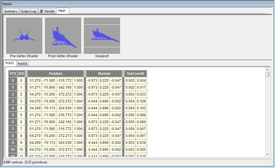
All that remains now is figuring out why my geometry is broken. I now have a clear understanding of what was wrong with everything else except my broken geometry problem. =(

I'm hoping someone will know of an article that correctly explains how I should have initialized my geometry so the rat nests I am rendering now can be fixed - because it seems simply copying the Vertices and Indices doesn't work the way I expected it to.

Game Render:
[attachment=17190:1.jpg]

Pix ( which doesn't show the skybox because my skybox uses a separate rendertarget )
[attachment=17195:2.jpg]

what the mesh looks like in pix:
[attachment=17191:3.jpg]

Wireframe:
[attachment=17193:4.jpg]


Edit: Corrected screenshots

Advertisement

You're getting there, instancing stream looks now good.

Edit: You know what ? I'd actually go a step back and draw the model normally without instancing at all. Then inspect with PIX and check what declaration (and strides) you get. I actually wonder if one can have different declarations for different parts. Maybe that's a another problem.

Edit2: Hmmm, my suspicion might hold. Get the vertex buffer from the ModelMeshPart and inspect the VertexDeclaration thereof (and show us).

The trouble here is that on my model ( in the non instanced exampled seen in the opening post ) , I needed to use different blendstates (engine glow built into the model requires alpha ). I also would like to be able to access individual mesh parts when rendering because I want some of my ships to have a spinning gravity ring without having to load a seperate model just to do it. Also some of my models will be huge, ( so big they could potentially extend all the way up to the end of my camera's view distance ) - in which I intend to LOD/OccludeTest individual mesh parts of a model ( large portions of supercapital ship, would be outside the camera's view frustum if you get close to it ).


While unsure how to get VertexStride and other buffer related data ( besides just the buffers themselves ) out of PIX, heres a check of what things look like to pix with my non instances test gamestate:

Primary Rendertarget from the end of the Final Compositor's compositing stage:
[attachment=17196:1.jpg]

Planets and Ships render to two seperate geometry buffers in my project ( planets require a much much larger draw distance )

What the fighter looks like in Pix:
[attachment=17197:2.jpg][attachment=17198:3.jpg]

What my Planet looks like in Pix:
[attachment=17199:4.jpg][attachment=17200:6.jpg]


Edit: Original Vertex Declaration
[attachment=17201:Clipboard03.jpg]

Edit: My Vertex declaration for comparison:
[attachment=17202:Clipboard02.jpg]

Not sure exaactly what it means, but I assume I should have manually specified a new vertex stride to accommodate my extra elements?

Im not exactly sure exactly what my Vertex Stride needs to be.

Edit: Also noticed now the positions of vertexes differ from the non instanced draw, as seen

post-213172-0-24179500-1375625369.jpg
post-213172-0-29462400-1375622272.jpg


Edit: This was being posted as your reply came in. Will try using VertexPositionNormalTexture
Well, I actuall meant VertexDeclaration.GetVertexElements. But now it's already obvious from that PIX screenshot. The vertex has normals so you should rather use VertexPositionNormalTexture when using VertexBuffer.GetData.
I changed it to VertexPositionNormalTexture .

Last PIX run final rendertarget:
[attachment=17203:1.jpg]

The first MeshPart of the above fighter model:
[attachment=17204:2.jpg]

Second and Third:
[attachment=17205:3.jpg]

[attachment=17206:4.jpg]


Also did an output with the shader set to translate normal to color, but I think this doesn't matter:
[attachment=17207:Clipboard02.jpg]

I am going braindead =(

While I can see differences in vertex positions compared to the original non instanced geometry's vertex positions, I am totally failing to understand still how they could be so different though.


Edit: Above numbers are with bone transforms applied, my mistake. This is the first mesh part without bone transforms applied:
[attachment=17208:Clipboard03.jpg]

When staring at my PIX screenshots this just hit me:

My semantics are getting scrambled. Vertex positions are mixing into the Normals and texture coordinate channels.... But why =( [edit - i think I understand why ]

[attachment=17209:Untitled-1.jpg]


Edit: -------------------

The two different models I have tested with supply different elements ( also, the fighter above has 5 total mesh parts across 3 meshes, while the other only has one total)

The elements supplied by the first original fighter ModelMeshPart: (which should be the same across all mesh parts )
[attachment=17210:1.jpg]

And elements from the other simpler model - the model were the strange extra texture coordinate was coming from:

[attachment=17211:2.jpg]

Which I dont understand, because both were modelled in 3DSMax and exported using the exact same FBX Exporter configuration in 3DSMax.


However with both models I get the same anomoly were vertex positions are mixed into the other element channels, in addition to being mixed in with other ( not needed ) elements. ( I dont need binormals or that pesky extra texture coordinate in this project)

The solution to my problem is now figuring out how to fix this problem and get onlt Position, Normal and TextureCoordinate into the output vertex buffers and work exactly the same for all models that I supply as long as they have the 3 elements I need, while discarding all extra elements.

If I figure this piece out now - then my problem is 1000% solved,.


But yeah - your suggestion to use PIX - Im loving this utility already. Makes no sense why no one else has ever mentioned it to me before.

Your original vertex data also has tangents and binormals. Make sure you have a struct which matches. It's probably like this:


[StructLayout(LayoutKind.Sequential)]
public struct VertexPNTTB
{
    public Vector3 Position;
    public Vector3 Normal;
    public Vector2 TexCoord;
    public Vector3 Tangent;
    public Vector3 Binormal;
}

Edit: Some additional comments.

I can't help you with 3DSMax, but I'm not surprised a model can have different formats. Either you go further with this, meaning "force" it to have one format only on the API side by converting/copying, or alternatively use the buffers and formats as-is like already suggested. For the latter you need to provide an additional matrix for the bone (shader constant) and draw the subsets separately. Maybe actually a better idea: Sounds like the parts need different states (blending) and maybe even different shaders anyway.

Nice fighter, by the way wink.png

PS: Yep, PIX is great.

Your original vertex data also has tangents and binormals. Make sure you have a struct which matches. It's probably like this:


[StructLayout(LayoutKind.Sequential)]
public struct VertexPNTTB
{
    public Vector3 Position;
    public Vector3 Normal;
    public Vector2 TexCoord;
    public Vector3 Tangent;
    public Vector3 Binormal;
}

The trouble though is thet the other model doesnt for some reason. I would like to eliminate Tangent and Binormal because none of my shaders actually use them ( while also eliminating the extra texturecoordinate the second model supplies ).

They way I thought about it was like this:

VertexBuffer.GetData(of Single)( temp, 'not sure how to calculate length' )

... with all of the original elements in a 1 dimensionall array, and coolecting only the Position, Normal, and TextureCoordinate from it, and discarding the rest. To completly replace the original elements.

this is under my understanding that using GetData to retrieve floats instead of structures will contain floats in this order :

1, Position ( 3 floats )
2, Normal ( 3 floats )
3, TextureCoordinate ( 2 floats )
...
4+ everything else

... loop -->

Dim Vertex As New VertexPositionNormalTexture

Vertex.Position = New Vector3(RAW(I), RAW(I + 1), RAW(I + 2))

Vertex.Normal = New Vector3(RAW(I + 3), RAW(I + 5), RAW(I + 6))

Vertex.TextureCoordinate = New Vector2(RAW(I + 7), RAW(I + 8))

' skip the unwanted data

I += StepSize

... <-- loop

so that regardless of how many elements a model loaded from FBX has declared, I would have replaced it with a vertex declaration that only contains the elements Position, Normal, TextureCoordinate, so that in the future if I encounter another model that defines unusual extra elements ( like a second texture Coordinate ), then It would have those stripped so that I can maintain an exact output element stream that is the same for all models.


EDIT:

The above worked exactly as I was hoping it would - by removing any elements manually that dont fit in VertexPositionNormalTexture, and fixed the errors in my VertexStream elements:
[attachment=17212:Clipboard05.jpg]


While there is probably a better way to do it, it at least allows me to prevent errors against models with variating element lengths - and ill probably need to improve on it:


I created this new subroutine:


        Private Function Get_Vertices(Part As ModelMeshPart) As VertexPositionNormalTexture()
            Dim OriginalElements As VertexElement() = {}

            OriginalElements = Part.VertexBuffer.VertexDeclaration.GetVertexElements

            Dim RAW As Single() = {}
 
            Dim I As Integer = 0 

            Dim Result As New List(Of VertexPositionNormalTexture)

            Dim StepSize = 8 ' number of floats per vertex

            ' TODO: maybe check all types?
            Dim Length = 0
            If OriginalElements.Length > 3 Then
                StepSize = 0
                For Each E As VertexElement In OriginalElements
                    If E.VertexElementFormat = VertexElementFormat.Vector2 Then
                        StepSize += 2


                    End If
                    If E.VertexElementFormat = VertexElementFormat.Vector3 Then
                        StepSize += 3
                    End If
                Next
            End If

            Dim L = (Part.VertexBuffer.VertexCount) * (StepSize) 

            Array.Resize(RAW, L)

            While I < RAW.Length - 1
                Dim Vertex As New VertexPositionNormalTexture

                Vertex.Position = New Vector3(RAW(I), RAW(I + 1), RAW(I + 2))

                Vertex.Normal = New Vector3(RAW(I + 3), RAW(I + 4), RAW(I + 5))

                Vertex.TextureCoordinate = New Vector2(RAW(I + 6), RAW(I + 7))

                ' skip the unwanted data

                I += StepSize

                Result.Add(Vertex)
            End While

            Return Result.ToArray
        End Function

And moodified my _Initialize_Geometry function the following:


.VertexBuffer.GetData(Of VertexPositionTexture)(Result_Vertex)

is now changed to


Result_Vertex = Get_Vertices(Part)

- were each vertex now only contains Position, Normal and TextureCoordinate , and remaining elements being discarded.


My code can do with a cleanup now - but now it's at least rendering the mesh correctly.

A bit more testing to try and verify weather Normal is stored before TextureCoordinate, or the other way around - just to make sure everything is correct... Texture Coordinate is working perfectly.

Pix Results:
[attachment=17214:1.jpg]
[attachment=17215:2.jpg]

I really appreciate the feedback. Your help was great.

Congrats, you're getting closer.

Hmmm, yeah, VertexBuffer.GetData has some overloads, but one still needs some type (currently your float). Pity one can't work with the blob directly, with VertexDeclaration.VertexStride and the offsets from the elements one could do this generically (see here for something along those lines). You could probably use a GetData(Of Byte) and some marshalling tricks to achieve that, but I doubt it will be simpler/easier than what you're doing now.

edited previous post D;


Im pretty confident now I can start implementing and experimenting with new features and carry on by myself again ( after I commit my source code to my repository - in case I break it ) - in addition to looking at how I could implement LOD with instancing.

I am pretty curious about using COLOR1,COLOR2,COLOR3 on a per instance level as well ( which is what I originally intended ). I think I could perhaps have my effect objects notify models of extra elements they would expect - or something....

And I can now update my existing shaders to make use of the instancing.

It feels a bit wierd because up till now everything else in my framework was written without help. But getting feedback definetly has it's perks - especially if it gets me looking at things differently or using tools I never knew existed that end up saving my brain from melting into a puddle of radioactive glowing yellow goo..

Once again m8, thanks for the feedback.

Hopefully in a few weeks my next forum thread here will be me showing off basic game-play features. Writing my game framework is full of l learning experiences.

This topic is closed to new replies.

Advertisement