1 Introduction
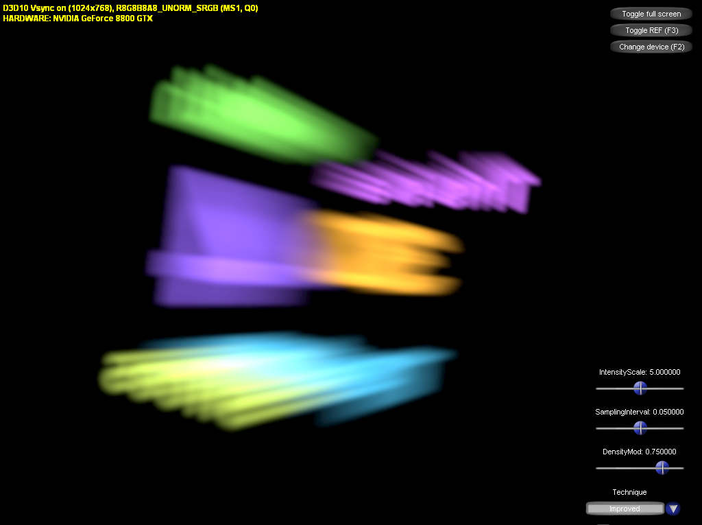
This article describes two simple implementations of the emission/absorption model for participating media. The model is evaluated per-pixel with ray-casting on the GPU. In addition to the obvious (and quite inflexible and ineffective) basic approach an optimized version is described. Source code is available for download.
The emission/absorption model for participating media basically states that at each point in a volume a certain amount of light is emitted (this can also include in-scattering) and and absorbed (this can include out-scattering). This article is focused on a practical implementation of the model, so I won't go into the theory. The model is derived and described in more detail in [1].
If the problem is discretized we get the familiar front-to-back compositing algorithm for each viewing ray:
I = 0.0;
T = 1.0;
i = n;
while( T > epsilon && i >= 1 )
{
  I = I + T*g[i];
  T = T*t[i];
  --i;
}
I = I + T*I0;
Here, n is the number of samples to be taken, I is the accumulated intensity (color), T is the accumulated transmittance, g[i] is the source term of the i-th ray segment, t[i] its transmittance, and I0 is the intensity that enters the volume (the background color).
If no early-ray termination (T £ e) is required (e.g. because it is extremely unlikely for the transmittance to drop below e), the algorithm above can more conveniently be written as a for-loop that accumulates a fixed number of samples:
I = 0.0;
T = 1.0;
for( int i=0; i<n; ++i )
{
  I = I + T*s[i];
  T = T*t[i];
}
I = I + T*I0;
The following two sections deal with implementing this algorithm on the GPU.
2 The basic version
This section contains a straightforward implementation of the model described above. This implementation has many shortcomings and should be regarded as a vehicle to explain the basic concepts, not so much as a serious suggestion of how to do it in a real-world application - although it may be good enough for some cases.
The approach taken here assumes the volume to be a box `filled' with a 3d texture (or a 2d texture extruded along the z-axis) that gives the values for g[i] and t[i]. `Filled' means the texture has to lie exactly in the box, i.e. the box has to cover the texture coordinates [0,1]3 uniformly (note that the box in world space can be transformed by an arbitrary affine transformation). The basic idea is to simply render the box, reconstruct the viewing ray for each covered pixel, and then calculate I and T with the algorithm given above.
2.1 Reconstructing the ray
The sampling will happen in texture space, so we need to find the segment of the viewing ray that lies in the cube [0,1]3 in texture space. Because we want to use the ray for sampling it is convenient to express the ray segment with a starting point, an increment vector (a vector with length equal to the sampling interval, Ds, pointing in the direction of the ray), and the number of samples to be taken.
For the simple case discussed here, the starting point of this segment (and the ray's direction in texture space) can easily be computed from the world position of the current fragment by applying a `World-To-Texture' transformation with a 4x4 matrix. However, I will describe a different approach. It may look more complicated and expensive (in fact it is, for the simple scenario chosen here), but it is more flexible and will come in handy in the following section, where a generalization of the technique is described.
The vertex shader passes the clip position and the z-component of the view-space position (a linear depth value) to the pixel shader. The following HLSL fragment shows how the segment is reconstructed from this information:
// First do the perspective division to get NDC
input.ClipPosition.xy /= input.ClipPosition.w;

// We can then use the 'focal lengths' to reconstruct the ray's
// direction in view space (note that it is not normalized, but
// has it's z-component set to 1).
float3 rayDir_VS = float3(
  input.ClipPosition.x / WorldToClip[0][0],
  input.ClipPosition.y / WorldToClip[1][1],
  1
  );

// Now it's easy to reconstruct the starting point and increment
// vector in view space...
float3 rayStart_VS = rayDir_VS * input.Depth;
float3 rayIncr_VS = normalize( rayDir_VS ) * g_SamplingInterval;

// ... and transform them to texture space
float3 rayStart_TS = mul( float4(rayStart_VS,1), g_ViewToTex ).xyz;
float3 rayIncr_TS = mul( rayIncr_VS, (float3x3)g_ViewToTex );
The number samples is effectively the number of times the increment vector can be added to the starting point before the resulting position no longer lies in the volume. Since we already have the increment vector in texture space, where the volume is [0,1]3, we can look at each axis separately and then take the minimum:
// This holds 'how many times can rayIncr_TS be applied before we
// run out of the unit cube'
float3 l = float3(
  rayIncr_TS.x > 0 ? (1-rayStart_TS.x)/rayIncr_TS.x
                   : -rayStart_TS.x/rayIncr_TS.x,
  rayIncr_TS.y > 0 ? (1-rayStart_TS.y)/rayIncr_TS.y
                   : -rayStart_TS.y/rayIncr_TS.y,
  rayIncr_TS.z > 0 ? (1-rayStart_TS.z)/rayIncr_TS.z
                   : -rayStart_TS.z/rayIncr_TS.z
  );

// The minimum of all three axes is our number of samples.
int numSamples = min( l.x, min(l.y, l.z) );

// Finally clamp numSamples to compensate for numerical
// problems and to convince the shader compiler that the
// sampling loop terminates after a finite number of
// iterations.
numSamples = clamp( 0, 1000, numSamples );
Now we have reconstructed all necessary parameters and can start sampling. The procedure described above may look quite expensive, especially when taking into account that it is executed in a pixel shader. There certainly is room for optimizations, but in most (interesting) cases the sampling process itself will be the dominant factor as far as run-time is concerned.
2.2 Sampling
The sampling process described in the introduction translates easily into HLSL code, only one thing has to be considered.
The appearance of the volume should be independent of the sampling interval, so it is reasonable to assume that the values given in the texture are per unit length. The source terms don't cause any problems, they simply have to be scaled down linearly by the sampling interval. The transmittance, however, is a problem. Because the absorption of light is an exponential process, there is no linear factor that one could use to scale the transmittance to match a certain sampling interval. If T is the transmittance per unit length and t is the transmittance of a distance Ds, the two are related by t=TDs. To avoid the pow function in the sampling loop I usually make the assumption that a) the volume is sampled with a fixed sampling interval and the transmittance values have been tweaked to match this particular interval, or b) there is no absorption at all.
This function does the sampling:
float4 Integrate_Fixed(
  float3 rayStart_TS, float3 rayIncr_TS,
  int numSamples, float4 samplingParams )
{
  float3 I = 0;
  float T = 1;
  float3 texCoord = rayStart_TS;
  for( int i=0; i<numSamples; ++i )
  {
    // take sample (rgb is source term, a is transmittance)
    float4 tex = g_EmiAbsTexture.SampleLevel(
      g_ClampedSampler, texCoord, 0 );

    // accumulate I and T
    I += T*tex.rgb;
    T *= pow( f.a, g_SamplingInterval );

    // step forward
    texCoord += rayIncr_TS;
  }
  I *= g_SamplingInterval;

  return float4( I, T );
}
2.3 Problems
The approach described so far is easy to implement, requires only one pass over the volume's geometry, and doesn't need any additional render targets. However, it has some serious limitations:
- It only works if the camera's near clipping plane is not intersecting the volume. If it does, the front faces for some pixels will be clipped away and no ray-casting will be performed for these pixels.
- The geometry is limited to a box, because of the algorithm used for ray-reconstruction.
- It does not produce correct results if solid geometry intersects the volume, because the ray-reconstruction doesn't take this into account.
- It uses a fixed and probably suboptimal sampling interval.
The next section contains some improvements that address these issues.
3 The improved version
First a generalization of the ray-reconstruction algorithm of the previous section is described, then two optimized sampling strategies are introduced.
3.1 Improving ray reconstruction
The improvements in this subsection let us correctly reconstruct rays for arbitrary convex volumes, even if the camera's near clipping plane or solid geometry intersect the volume. However, in order to reach this goal we need two additional render targets: a linear depth buffer that stores the z-component of view space coordinates of solid objects (which you probably have anyway) and another depth buffer that stores the depths of front-facing fragments of the volume(s). Having these render targets in back buffer resolution is often a waste of resources (memory and time) - in most cases it is sufficient to do the ray-casting at a lower resolution and blend the result into the back buffer (see section 3.3). The basic outline of the algorithm is as follows:
- Render solid objects to color and depth buffer (initialized with clipFar)
- Lay down depths of front faces of volume in second depth buffer (initialized with clipNear)
- Render back faces of volume to color buffer (without z-test), doing the ray-casting
With the help of the two depth buffers and the depth of the volume's back faces, the depths of the ray's entry and exit point can easily be reconstructed:
input.ClipPosition.xy /= input.ClipPosition.w;
float2 screenTexCoord =
  input.ClipPosition*float2(0.5, -0.5) + float2(0.5,0.5);

float3 rayDir_VS = float3(
  input.ClipPosition.x * g_SamplingParams.z,
  input.ClipPosition.y * g_SamplingParams.w,
  1
  );

// startDepth is always correct, even if front facing fragments
// have been clipped away (then the texture holds clipNear).
float startDepth = g_VolumeDepthTexture.Sample(
  g_ClampedPointSampler, screenTexCoord );

// endDepth is the backside of the volume or the solid geometry,
// whichever is nearer.
float sceneDepth = g_SolidDepthTexture.Sample(
  g_ClampedPointSampler, screenTexCoord );
float endDepth = min( input.Depth, sceneDepth );

// Clip fragments that are completely behind solid geometry
clip( endDepth - startDepth );
These depths can be used to init the ray parameters as shown in the previous section. But with a minor modification to this technique an improved sampling pattern can be implemented.
3.2 Improving sampling
It is usually not beneficial to take (much) more than one sample per texel, because more samples would make the same contribution. If trilinear interpolation is used this is not really true, but to adjust the sampling interval to the function that is to be sampled is always a good idea. To achieve this, the increment vector in texture space should be scaled, so that the magnitude of it's largest component is as big as (or slightly smaller as) a texel projected onto the corresponding axis.
If we have a vector in texture space pointing from the ray's entry to it's exit point, we first have to multiply it by the texture's resolution to get texel-relative coordinates. Then we need to find the component with the largest absolute value and divide the original vector from entry to exit point by this absolute value. This yields an increment vector in texture space that spans exactly one texel.
The following HLSL fragment shows the complete procedure:
float3 rayStart_VS = rayDir_VS * startDepth;
float3 rayEnd_VS = rayDir_VS * endDepth;
float3 rayDiff_VS = rayDir_VS * (endDepth-startDepth);

// Get vector from entry to exit point in texture space.
float3 rayDiff_TS = mul( rayDiff_VS, (float3x3)g_ViewToTex );

// Scale it to span one texel.
float3 m = abs( rayDiff_TS ) * g_TextureSize;
float scale = 1.0 / max( m.x, max(m.y, m.z) );
float3 rayIncr_TS = rayDiff_TS * scale;

// Set up numSamples and samplingInterval.
// They can be calculated from length ratios.
int numSamples = length(rayDiff_TS) / length(rayIncr_TS);
numSamples = clamp( 0, 1000, numSamples );
float samplingInterval = 1.0/numSamples * length( rayDiff_VS );

// Finally move the starting point one half increment vector
// inside the volume in the hope to sample close to centroids
float3 rayStart_TS = mul( float4(rayStart_VS,1), g_ViewToTex ).xyz;
rayStart_TS += rayIncr_TS * 0.5;
This is a kind of `half-adaptive' sampling, because the sampling interval can be different for individual rays, but is constant along each ray. If the alpha channel in the texture is not needed to code transmittance, it can be used to implement a simple form of (fully) adaptive sampling. Then the alpha value of each texel can code how many texels you can walk at least in every direction before the value of the texture changes. This information can be used inside the sampling loop to make larger steps in regions where the value of the texture doesn't change. This technique can provide big performance gains for textures that have mostly low-frequency content (which often will be the case).
3.3 Trading quality for speed
If the texture resolution and the position of the volume on screen (screen area and depth) are fixed, the sampling rate is the only variable that can effectively be used to balance speed versus quality. Even with the optimizations described in the previous subsection, the ray-casting process can be quite costly. So for some applications more aggressive optimizations may be necessary.
The obvious way to reduce rendering costs is to reduce the sampling rate `in-depth', i.e. the sampling rate along each ray. However, this quickly produces objectionable artifacts (visible slices). Another way to reduce the sampling rate is to reduce the pixel coverage by doing the ray-casting calculations at a lower resolution. This approach also causes artifacts when one tries to combine the ray-casting buffer with a higher resolution render target (jagged edges).
Both types of artifacts can be fought quite effectively with blurring. With a moderate amount of blurring, the resolution of the ray-casting buffers can be halved or quartered for many applications without loosing too much quality. Additionally, the sampling rate along each ray can also be reduced, because the slice artifacts will also be hidden by the blurring.
Another strategy to reduce sampling costs is to reduce the texture resolution or to compress the texture. Besides the obvious consequence that less samples are needed to render with a smaller texture, reducing the texture's size in memory can also greatly improve cache-efficiency during the sampling process.
4 Conclusion
Two implementations of the emission/absorption model for participating media have been described, a simple, straightforward approach and a more flexible, improved approach. The first works in back-buffer resolution with a fixed sampling rate and does not require additional buffers. Because it imposes several restrictions to the scene it is not very practical for most real-world applications. The second approach removes these restrictions and allows for a better trade-off between quality and speed, but needs additional buffers.
References
[1] Nelson Max. Optical models for direct volume rendering. IEEE Transactions on Visualization and Computer Graphics, 1(2):99-108, 1995.