Finding the bounds for a set of triangles is one of the most frequently-performed computations in games. It is fundamental to collision detection, scene culling, and ray tracing. Performing it on the GPU offloads work from the CPU, and can be an order of magnitude faster. The axis-aligned bounding box, or AABB, can be represented as 6 planes:
struct AABB
{
	float Left;
	float Right;
	float Top;
	float Bottom;
	float Near;
	float Far;
};
Perhaps a more common alternative is simply storing two points for the corners:
struct AABB
{
	Vector3 MinCorner;
	Vector3 MaxCorner;
};
CPU pseudocode to compute the bounding box over a set of points is trivial:
AABB aabb;
aabb.MinCorner = (MaxFloat, MaxFloat, MaxFloat);
aabb.MaxCorner = (-MaxFloat, -MaxFloat, -MaxFloat);
for each vertex in buffer
{
	aabb.MinCorner.x = Min(vertex.x, aabb.MinCorner.x);
	aabb.MinCorner.y = Min(vertex.y, aabb.MinCorner.y);
	aabb.MinCorner.z = Min(vertex.z, aabb.MinCorner.z);

	aabb.MaxCorner.x = Max(vertex.x, aabb.MaxCorner.x);
	aabb.MaxCorner.y = Max(vertex.y, aabb.MaxCorner.y);
	aabb.MaxCorner.z = Max(vertex.z, aabb.MaxCorner.z);
}
If you wish to leverage D3DX, simply use the
D3DXComputeBoundingBox function to perform the above operation.
Na?ve GPU Approach: Leverage the Depth Buffer
The aforementioned loop is embarrassingly parallelizable and therefore well-suited to the GPU. Using a general-purpose computation language like NVIDIA's CUDA technology would make this easy, but it is often desirable to stay within the confines of the graphics API itself. How could we use the graphics API to perform a computation like this? The divide-and-conquer philosophy tells us to approach the problem by solving its sub-problems first. It can be helpful to think about only one dimension at a time. If we can simply compute the near plane, then we should be able to compute the other five planes via transformations.
Finding the "nearest" point is something fundamental to real-time graphics. Anyone familiar with OpenGL or D3D knows that where there is 3D rendering, a depth buffer lurks beneath:
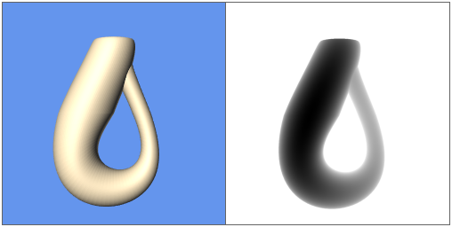
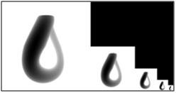
Note that we are interested in only
one depth value, while the depth buffer represents
many depth values. The trick is to render to a 1x1 viewport. It's difficult to visualize rendering an entire model into a 1x1 area, so it may help to think of it as the end of a continuously shrinking viewport:
Aside: Depth Buffer Visualization with Direct3D 10
To produce a grayscale visualization of the depth buffer similar to the pictures in this article, one approach using D3D10 is the following:
- Create a texture that has a color format equivalent to the depth buffer format. For example, if the depth buffer is DXGI_FORMAT_D32_FLOAT, then the texture should have a format of DXGI_FORMAT_R32_FLOAT. The texture should have the same width and height as the render target.
- After rendering the scene as you normally would, un-bind the depth buffer by passing null into the last argument of ID3D10Device::OMSetRenderTargets().
- Use ID3D10Device::CopyResource() to copy the values from the real depth buffer into the grayscale texture from step 1.
- Bind the grayscale texture to a pixel shader resource and draw it to the screen using a full-screen quad.
An example of this procedure can be found in the sample code attached to this article.
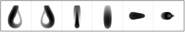
Since the nearest point always trumps the points that render behind it, the depth buffer of our 1x1 render target should hold the nearest Z value. Computing values for the other five planes can be achieved by simply rotating the model appropriately:
There are some caveats to using the depth buffer in this way:
- Be sure to use a high-precision depth buffer. In the case of D3D10, use DXGI_FORMAT_D32_FLOAT when creating your depth texture. Remember that the viewport is only 1x1, so the performance implication of this is relatively unimportant.
- Because we are rendering to a 1x1 viewport, each triangle takes up a screen area that is only a fraction of a pixel. This can lead to rendering only one interior point per triangle, which results in an incorrect bounding box. To bypass this issue, use point primitives rather than triangles. In the case of D3D10, set your primitive topology to D3D10_PRIMITIVE_TOPOLOGY_POINTLIST.
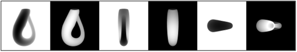
It seems cumbersome to re-render the object in 6 different orientations. One idea is to use only three rotations, then set the graphics API to use reverse testing for each "Max" plane, as depicted here:
To achieve this with D3D10, set your
DepthFunc to
GREATER_EQUAL rather than the default
LESS. Also be sure to change your clear value appropriately. So, your effect file would look as follows:
DepthStencilState MyDepthState
{
	DepthEnable = TRUE;
	DepthFunc = LESS GREATER_EQUAL;
	DepthWriteMask = ALL;
};
And your clear call would look like this:
device->ClearDepthStencilView(depthView, D3D10_CLEAR_DEPTH, 1 0, 0);
Unfortunately, this approach is not much of an improvement as it still requires a total of 6 rendering passes. How can we reduce the number of passes down to 1 or 2?
Exploit the Blending Hardware
When rendering, we typically render to a color buffer, not just a depth buffer alone. Each pixel in our 1x1 render target has slots for red, green, and blue that we've been ignoring. The secret sauce lies in the blending hardware. Typically, blending is used to compute a simple weighted sum, as in:
ac[sub]src[/sub]+(1-a)
c[sub]dest[/sub]
However, graphics APIs typically allow more than just addition, as seen in the following table.
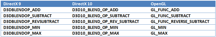
Those last two rows should catch your eye!
Before we can use these blending operations, we should make sure that we're rendering into a floating-point render target. In D3D10, this can be done with
DXGI_FORMAT_R32G32B32A32_FLOAT. Despite the fact that we're exploiting the hardware's blending stage, we actually will
not be using the alpha channel. We specify alpha in our format only because it is typically required by the API when specifying a render target. So, by simply writing X Y Z into our R G B channels while using MIN blending for the first pass, and MAX blending for the second pass, we can compute a complete bounding box! The D3D10 HLSL for this technique follows.
struct VS_OUTPUT
{
	float4 Position : SV_POSITION;
	float4 Pretransformed : POSITIONT;
};

VS_OUTPUT FindBoundsVS(float4 Position : POSITION)
{
	VS_OUTPUT Output;
	Output.Position = float4(0, 0, 0, 1);
	Output.Pretransformed = Position;
	return Output;
}

float4 FindBoundsPS(VS_OUTPUT In)  : SV_TARGET
{
	return In.Pretransformed;
}
Since we're rendering into a 1x1 viewport, the vertex shader sets the outgoing position to (0, 0, 0), then writes the pretransformed position out to the pixel shader, which simply writes it out into the floating-point render target.
To read the values of our bounding box out from the render target, we'll need to copy the values into a "staging area" that can be accessed from the CPU. Because of this copy, which is slow, it is best to actually render to a 2x1 texture, and shift the 1x1 viewport between passes, allowing us to copy only once instead of twice. Summarizing the technique for D3D10:
- Create two floating-point 2x1 textures with the following parameters:
- BindFlags = RENDER_TARGET, CPUAccessFlags = 0, Usage = DEFAULT
- BindFlags = 0, CPUAccessFlags = READ, Usage = STAGING
- Bind the output merger stage to the 2x1 render target texture.
- Set the viewport to 1x1 with TopLeft at (0, 0).
- Set the blending state to use BlendOp = MIN, SrcBlend = SRC_COLOR, DestBlend = DEST_COLOR.
- Render the geometry using the pass-through shaders described above.
- Move the viewport's TopLeft to (1,0)
- Change the BlendOp to MAX.
- Render the geometry again.
- Unbind the output merger stage from the 2x1 render target.
- Call ID3D10Device::CopyResource() to copy data from the render target texture to the staging texture.
- Call ID3D10Texture2D::Map() on the staging texture to read the values of the two corners from the color buffer.
Conclusion
If you've got your API state set up correctly, computing a bounding-box can be as simple as re-rendering the object into a 1x1 viewport and reading back the color values. The GPU represents an enormous amount of computing power that is now typical in every home PC. By thinking outside the box (no pun intended), it's easy to find new and interesting ways to offload work from the CPU.