(Last modification: April 1st, 2002)
The final output of any 3D graphics hardware consists of pixels. Depending on the resolution, in excess of 2 million pixels may need to be rendered, lit, shaded and colored. Prior to DirectX 8.0, Direct3D used a fixed-function multitexture cascade for pixel processing. The effects possible with this approach were very limited on the implementation of the graphics card device driver and the specific underlying hardware. A programmer was restricted on the graphic algorithms implemented by these.
With the introduction of shaders in DirectX 8.0 and the improvements of pixel shaders in DirectX 8.1, a whole new programming universe can be explored by game/demo coders. Pixel shaders are small programs that are executed on individual pixels. This is an unprecedented level of hardware control for their users.
The third part in this "Introduction to Shader Programming", named "Fundamentals of Pixel Shaders", shows you
- the place and the tasks of pixel shaders in the Direct3D pipeline
- the architecture of the pixel shader unit
- tools, that help to program pixel shaders
- the ingredients for a pixel shader-driven application
[size="5"]Why use Pixel Shaders?
Pixel shaders are at the time of this writing supported by GeForce 3/4TI and RADEON 8500-based cards. Unlike vertex shaders, however, there is no feasible way of emulating pixel shaders using software.
The best argument for using pixel shaders is to take a look at a few demos that uses them :-) ... or just one word: per-pixel non-standardized lighting. The gain in visual experience is enormous. You can use membrane shaders, for balloons, skins, kubelka-munk shaders for translucency effects, fur/hair shaders and new lighting formulas that lead to a totally new lighting experience. Think of a foreign planet with three moons moving faster than the two suns or with a planet surface consisting of different crystalline substances, reflecting light in different ways. The following list should give you a glimpse on the many types of effects that are possible by using pixel shaders now:
- Single pass, per-pixel lighting (see next part)
- True phong shading [Beaudoin/Guardado]
- Anisotropic lighting [Isidoro/Brennan]
- Non-Photorealistic-Rendering: cartoon shading, hatching, gooch lighting, image space techniques [Card/Mitchell]
- Per-pixel fresnel term [Brennan]
- Volumetric effects [Kraus][Hart]
- Advanced bump mapping (self-shadowing bump maps (also known as Horizon Mapping)
- Procedural textures [Zecha] and texture perturbation [Isidoro/Riguer]
- Bidirectional reflectance distribution functions [Morav?nsky]
One of the biggest catches of pixel shaders is that they often have to be "driven" by the vertex shader. For example to calculate per-pixel lighting the pixel shader needs the orientation of the triangle, the orientation of the light vector and in some cases the orientation of the view vector. The graphics pipeline shows the relationship between vertex and pixel shaders.
[size="5"]Pixel Shaders in the Pipeline
Figure 1 - Direct3D Pipeline
The following diagram shows the DX6/7 multitexturing unit and the new pixel shader unit. On pixel shader-capable hardware, the pixel shader heightens the number of transistors on the graphic chip, because it is added to the already existing DX 6/7 multitexturing hardware. Therefore it is also functionally an independent unit, that the developer can choose instead of the DX6/7 multitexturing unit.
But what happens in the 3D pipeline before the pixel shader? A vertex leaves the Vertex Shader as a transformed and colored vertex. The so-called Backface Culling removes all triangles, that are facing away from the viewer or camera. These are by default the vertices that are grouped counter-clockwise. On average, half of your game world triangles will be facing away from the camera at any given time, so this helps reducing rendering time. A critical point is the usage of translucent or transparent front triangles. Depending on what is going to be rendered, Backface culling can be switched off with the D3DCULL_NONE flag.
[bquote]Backface Culling uses the crossproduct of two sides of a triangle to calculate a vector that is perpendicular to the plane that is formed by these two sides. This vector is the face normal. The direction of this normal determines whether the triangle is front- or backfacing. Because the Direct3D API always uses the same vertex order to calculate the crossproduct, it is known whether a triangle's vertices are "wound" clockwise or counter-clockwise.[/bquote]
User Clip Planes can be set by the developer to clip triangles with the help of the graphics card, that are outside of these planes and therefore to reduce the number of calculations. How to set User Clip Planes is shown in the Direct3D 8.1 example named "Clip Mirror" and in the ATI RADEON 8500 Nature demo. The RADEON and RADEON 8500 support six independant user clip planes in hardware. The clip planes on the GeForce 1/2/3/4TI chips are implemented using texture stages. That means that two User Clip Planes you use, eat up one texture stage.[bquote]It looks like NVIDIA no longer exposes the cap bits for these.The DirectX Caps Viewer reports MaxUserClipPlanes == 0 since the release of the 12.41 drivers.[/bquote]
One alternative to clip planes is shown in the "TexKillClipPlanes" example delivered in the NVIDIA Effects Browser, where the pixel shader instruction texkill is used to get a similar functionality like clip planes.Another alternative to clip planes is guard band clipping as supported by GeForce hardware [Dietrich01]. The basic idea of guard band clipping is that hardware with a guard band region can accept triangles that are partially or totally off-screen, thus avoiding expensive clipping work. There are four cap fields for Guard Band support in the D3DCAPS8 structure: GuardBandLeft, GuardBandRight, GuardBandTop, and GuardBandBottom. These represent the boundaries of the guard band. These values have to be used in the clipping code. Guard band clipping is handled automatically by switching on clipping in Direct3D.
Frustum Clipping is performed on the viewing frustum. Primitives that lie partially or totally off-screen must be clipped to the screen or viewport boundary, which is represented by a 3D viewing frustum. The viewing frustum can be visualized as a pyramid, with the camera positioned at the tip. The view volume defines what the camera will see and won't see. The entire scene must fit between the new and far clipping planes and also be bounded by the sides, the bottom and top of the frustum. A given object in relation to the viewing frustum can fall into one of three categories [Watt92]:
- The object lies completely outside the viewing in which case it is discarded.
- The object lies completely inside the viewing frustum, in which case it is passed on to the Homogenous Divide.
- The object intersects the viewing frustum, in which case it is clipped against it and then passed on to the Homogenous Divide.
-w [lessthan]= x [lessthan]= w
-w [lessthan]= y [lessthan]= w
0 [lessthan]= z [lessthan]= w
This would be a slow process, if it has to be done by the CPU, because each edge of each triangle that crosses the viewport boundary must have an intersection point calculated, and each parameter of the vertex ( x,y,z diffuse r,g,b, specular r,g,b, alpha, fog, u and v ) must be interpolated accordingly. Therefore frustrum clipping is done by modern graphics hardware on the GPU essentially for free with clip planes and guard band clipping.
After Frustrum clipping, the Homogenous or perspective Divide happens. This means that the x-, y- and z-coordinates of each vertex of the homogenous coordinates are divided by w. The perspective divide makes nearer objects larger, and further objects smaller as you would expect when viewing a scene in reality. After this division, the coordinates are in a normalized space:
-1 [lessthan]= x/w [lessthan]= 1
-1 [lessthan]= y/w [lessthan]= 1
0 [lessthan]= z/w [lessthan]= 1
[bquote]Why do we need this divide through w? By definition every point gets a fourth component w that measures distance along an imaginary fourth-dimensional axis called w. For example, (4, 2, 8, 2) represents the same point as (2, 1, 4, 1). Such a w-value is useful for example to translate an object, because a 3x3 matrix is not able to translate an object without changing its orientation. The fourth coordinate, w, can be thought of as carrying the perspective information necessary to represent a perspective transformation.[/bquote]
Clip coordinates are also referred to as normalized device coordinates (NDC). These coordinates are now mapped to the screen by transforming into screen space via the so-called Viewport Mapping. To map these NDCs to screen space, the following formula is used for a resolution of 1024x768:ScreenX(max) = NDC(X) * 512 + 512
ScreenY(max) = NDC(Y) * 384 + 384The minimum and maximum value of X and Y is (-1, -1) to (1, 1). When the NDC's are (-1, -1), the screen coordinates areScreenX = -1 * 512 + 512
ScreenY = -1 * 384 + 384This point lies in the upper-left corner. For example the lower-right corner will be reached with NDCs of (1, 1). Although z and w values are retained for depth buffering tests, screen space is essentially a 2D coordinate system, so only x and y values need to be mapped to screen resolution.Now comes the Triangle Setup, where the life of the vertices end and the life of the pixel begins. It computes triangle for triangle the parameters required for the rasterization of the triangles, amongst other things it defines the pixel-coordinates of the triangle outline. This means that it defines the first and the last pixel of the triangle scan line by scan line:
Figure 2 - Triangle Setup
Then the Rasterizer interpolates color and depth values for each pixel from the color and depth values of the vertices. These values are interpolated using a weighted average of the color and depth values of the edge's vertex values, where the color and depth data of edge pixels closer to a given vertex more closely approximate values for that vertex. Then the rasterizer fills in pixels for each line.
Figure 3 - Filled Triangle
In addition, the texture coordinates are interpolated for use during the Multitexturing/Pixel Shader stage in a similar way.
The rasterizer is also responsible for Direct3D Multisampling. Because it is done in the Rasterizer stage, Multisampling only affects triangles and group of triangles; not lines. It increases the resolution of polygon edges and therefore as well as depth and stencil tests. The RADEON 7x00/GeForce 3 supports this kind of spatial anti-aliasing by setting the D3DRASTERCAPS_STRECHBLTMULTISAMPLE flag, but both ignore the D3DRS_MULTISAMPLEMASK render state to control rendering into the sub-pixel samples, whereas the RADEON 8500 is able to mask the sub-samples with different bit-pattern by using this render state. By affecting only specific sub-samples, effects like motion blur or depth of field and others can be realized.
[bquote]Alternatively, motion blur and depth of field effects are possible with the help of vertex and pixel shaders; see the NVIDIA examples in the Effects Browser.
GeForce 3/4TI, RADEON 7x00 and RADEON 8500 chips have another stage in between the triangle setup and the pixel shader. Both chips has a visibility subsystem that is responsible for z occlusion culling. In case of the ATI cards it is called Hierarchical-Z. It determines if a pixel will be hidden behind an earlier rendered pixel or not. If the z occlusion culling should determine that the pixel is hidden it will directly be discarded and it won't enter the pixel shader, thus saving the initial z-buffer read of the pixel-rendering pipeline. During scan line conversion, the screen is divided into 8x8 pixel blocks (RADEON 7x00) or 4x4 pixel blocks (RADEON 8500), and each block is assigned a bit that determines whether that block is "not cleared", that means visible or "cleared", that means occluded. A quick z-check is performed on each of these blocks to determine whether any pixels in them are visible. If a pixel in a block is visible, the status bit is flipped to visible and the new z-value for that pixel is written to the z-buffer. If the block is not visible, its status bit remains set to occluded and the z-buffer isn't touched. The whole block will not be send to the pixel shader.
Sorting objects or object groups from front to back when rendering helps z-culling to kick out pixels from the gaphics pipeline very early, saving not only a write into the z-buffer (as with texkill), but also a read of the z-buffer.[/bquote]
The Pixel Shader is not involved on the sub-pixel level. It gets the already multisampled pixels along with z, color values and texture information. The already Gouraud shaded or flat shaded pixel might be combined in the pixel shader with the specular color and the texture values fetched from the texture map. For this task the pixel shader provides instructions that affect the texture addressing and instructions to combine the texture values in different ways with each other.GeForce 3/4TI, RADEON 7x00 and RADEON 8500 chips have another stage in between the triangle setup and the pixel shader. Both chips has a visibility subsystem that is responsible for z occlusion culling. In case of the ATI cards it is called Hierarchical-Z. It determines if a pixel will be hidden behind an earlier rendered pixel or not. If the z occlusion culling should determine that the pixel is hidden it will directly be discarded and it won't enter the pixel shader, thus saving the initial z-buffer read of the pixel-rendering pipeline. During scan line conversion, the screen is divided into 8x8 pixel blocks (RADEON 7x00) or 4x4 pixel blocks (RADEON 8500), and each block is assigned a bit that determines whether that block is "not cleared", that means visible or "cleared", that means occluded. A quick z-check is performed on each of these blocks to determine whether any pixels in them are visible. If a pixel in a block is visible, the status bit is flipped to visible and the new z-value for that pixel is written to the z-buffer. If the block is not visible, its status bit remains set to occluded and the z-buffer isn't touched. The whole block will not be send to the pixel shader.
Sorting objects or object groups from front to back when rendering helps z-culling to kick out pixels from the gaphics pipeline very early, saving not only a write into the z-buffer (as with texkill), but also a read of the z-buffer.[/bquote]
There are five different pixel shader standards supported by Direct3D 8.1. Currently, no pixel shader capable graphics hardware is restricted on the support of ps.1.0. Therefore all available hardware supports at least ps.1.1. So I will not mentioned the legacy ps.1.0 in this text anymore. ps.1.1 is the pixel shader version that is supported by GeForce 3. GeForce 4TI supports additionally ps.1.2 and ps.1.3. The RADEON 8x00 supports all of these pixel shader versions plus ps.1.4.
Whereas the ps.1.1, ps.1.2 and ps.1.3 are, from a syntactical point of view, build on each other, ps.1.4 is a new and more flexible approach. ps.1.1 - ps.1.3 differentiate between texture address operation instructions and texture blending instructions. As the name implies, the first kind of instructions is specialized and only usable for address calculations and the second kind of instructions is specialized and only usable for color shading operations. ps.1.4 simplifies the pixel shader language by allowing the texture blending (color shader) instruction set to be used for texture address (address shader) operations as well. It differentiate between arithmetic instructions, that modify color data and texture address instructions, that process texture coordinate data and in most cases sample a texture.
[bquote]Sampling means looking up a color value in a texture at the specified up to four coordinates (u, v, w, q) while taking into account the texture stage state attributes.[/bquote]
One might say that the usage of the instructions in ps.1.4 happens in a more RISC-like manner, whereas the ps.1.1 - ps.1.3 instruction sets are only useable in a CISC-like manner.This RISC-like approach will be used in ps.2.0, that will appear in DirectX 9. Syntactically ps.1.4 is compared to ps.1.1-ps.1.3 an evolutionary step into the direction of ps.2.0.
What are the other benefits of using ps.1.4?
- Unlimited texture address instructions: Direct3D 8.0 with ps.1.1 is restricted to a small number of meaningful ways in which textures can be addressed. Direct3D 8.1 with ps.1.4 allows textures to be addressed and sampled in a virtually unlimited number of ways, because the arithmetic operation instructions are also usable as texture address operation instructions.
- Flexible dependent texture reads.
- RADEON 8x00 performs ps.1.4 faster than ps.1.1 - ps.1.3, because the latter is emulated.
- All of the upcoming graphics hardware that will support ps.2.0, will support ps.1.4 for backward compatibility.
The Alpha Test stage kicks out pixels with a specific alpha value, because these shouldn't be visible. This is for example one way to map decals with an alpha mapped texture. The alpha test is switched on with D3DRS_ALPHATESTENABLE. The incoming alpha value is compared with the reference alpha value, using the comparison function provided by the D3DRS_ALPHAFUNC render state. If the pixel passes the test, it will be processed by the subsequent pixel operation, otherwise it will be discarded.
Alpha test does not incur any extra overhead, even if all the pixels pass the test. By tuning appropriately the reference value of Alpha Test to reject the transparent or almost transparent pixels, one can improve the application performance significantly, if the application is memory bandwidth fill-bound. Basically, varying the reference value acts like a threshold setting up how many pixels are going to be evicted. The more pixels are being discarded, the faster the application will run.
There is a trick to drive the alpha test with a pixel shader, that will be shown later in the section on swizzling. The image-space outlining technique in [Card/Mitchell] uses alpha testing to reject pixels that are not outlines and consequently improve performance.
The Stencil Test masks the pixel in the render target with the contents of the stencil buffer. This is useful for dissolves, decaling, outlining or to build shadow volumes [Brennan]. A nice example for this is "RadeonShadowShader", that could be found on the ATI web-site.
The Depth Test determines, whether a pixel is visible by comparing its depth value to the stored depth value. An application can set up its z-buffer z-min and z-max, with positive z going away from the view camera in a left-handed coordinate system. The Depth test is a pixel-by-pixel logical test that asks "Is this pixel in back of another pixel at this location?". If the answer returned is yes, that pixel gets discarded, if the answer is no, that pixel will travel further through the pipeline and the z-buffer is updated. There is also a more-precise and bandwidth saving depth buffer form called w-buffer. It saves bandwidth by having only to send x/y/w coordinates over the bus, while the z-buffer in certain circumstances has to send all that plus z.
[bquote]It is the only depth buffering method used by the Savage 2000-based boards. These cards emulate the z-buffer with the help of the hardware w-buffer.
When using vertex shaders with w-buffering on a GeForce 3/4TI card, make sure the projection matrix is set in the traditional way (using SetTransform()), otherwise w-buffering won't work correctly (Read more in the GeForce 3 FAQ, which can be found at www.nvidia.com/developer).[/bquote]
The pixel shader is able to "drive" the depth test with the texdepth (ps.1.4 only) or the texm3x2depth (ps.1.3 only) instructions. These instructions can calculate the depth value used in the depth buffer comparison test on a per-pixel basis.When using vertex shaders with w-buffering on a GeForce 3/4TI card, make sure the projection matrix is set in the traditional way (using SetTransform()), otherwise w-buffering won't work correctly (Read more in the GeForce 3 FAQ, which can be found at www.nvidia.com/developer).[/bquote]
The Alpha Blending stage blends the pixel's data with the pixel data already in the Render Target. The blending happens with the following formula:
FinalColor = SourcePixelColor * SourceBlendFactor +

         	DestPixelColor * DestBlendFactor
There are different flags, that can be set with the D3DRS_SRCBLEND (SourceBlendFactor) and D3DRS_DESTBLEND (DestBlendFactor) parameters in a SetRenderState() call. Alpha Blending was formerly used to blend different texture values together, but nowadays it is more efficient to do that with the multitexturing or pixel shader unit, depending on hardware support. Alpha Blending is used on newer hardware to simulate different levels of transparency.Dithering tries to fool the eye into seeing more colors than are actually present by placing different colored pixels next to one another to create a composite color that the eye will see. For example using a blue next to a yellow pixel would lead to a green appearance. That was a common technique in the days of the 8-bit and 4-bit color systems. You switch on the dithering stage globally with D3DRS_DITHERENABLE.
The Render Target is normally the backbuffer in which you render the finished scene, but it could be also the surface of a texture. This is useful for the creation of procedural textures or for the re-usage of results of former pixel shader executions. The render target is read by the stencil- , depth test and the alpha blending stage.
To summarize the tasks of the pixel shader in the Direct3D pipeline:
- The pixel shader is fed with rasterized pixels, which means in most cases z-occlussion culled, multisampled and already gouraud-shaded pixels
- The pixel shader receives an interpolated texture coordinate, interpolated diffuse and specular colors
- There are mainly four flavours of pixel shaders, the ps.1.1 - ps.1.3 standards are from a syntactical point of view a more CISC-like approach, whereas the ps.1.4 standard uses a RISC-like approach, that will be used in the upcoming ps.2.0
- The pixel shader delivers the shaded pixel to the fog stage
- The pixel shader is able to support or drive the consecutive Direct3D stages
[size="5"]Pixel Shader Tools
I already introduced Shader Studio, Shader City, DLL Detective, 3D Studio Max 4.x/gmax, NVASM, the Effectsbrowser, the Shader Debugger and the Photoshop plug-ins from NVIDIA in the first part. There is one thing to remember specific for pixel shaders: because the GeForce 4TI supports ps.1.1 - ps.1.3, it is possible, that a few of the NVIDIA tools won't support ps.1.4. Additionally there are the following pixel shader-only tools:
[size="3"]Microsoft Pixel Shader Assembler
The pixel shader assembler is provided with the DirectX 8.1 SDK. Like with it's pendant the vertex shader assembler it does not come with any documentation. Its output look like this:
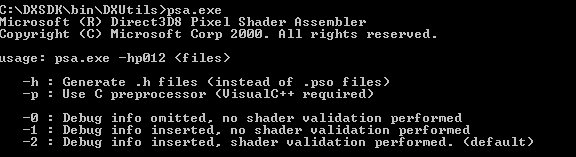
Figure 4 - Pixel Shader Assembler Output
The pixel shader assembler is used by the Direct3DX functions that compile pixel shaders and can also be used to pre-compile pixel shaders.
[size="3"]MFC Pixel Shader
The MFC Pixel Shader example provided with the DirectX 8.1 SDK comes with source. It is very useful for trying out pixel shader effects in a minute and debugging them. Just type in the pixel shader syntax you want to test and it will compile it at once. Debugging information is provided in the window at the bottom. If your graphics card doesn't support a particular pixel shader version, you can always choose the reference rasterizer and test all desired pixel shader versions. In the following picture the reference rasterizer was chosen on a GeForce 3 to simulate ps.1.3:
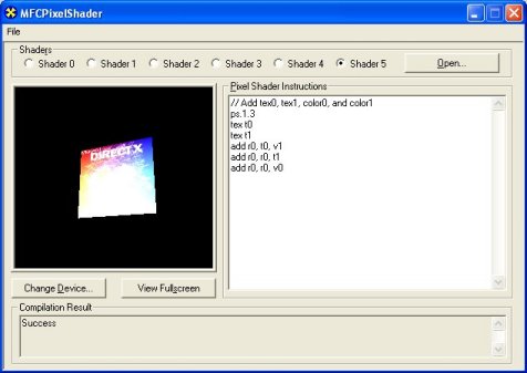
Figure 5 - MFCPixelShader
[size="3"]ATI ShadeLab
The ATI Shadelab helps designing pixel shaders. After writing the pixel shader source into the big entry field in the middle, the compilation process starts immediately. To be able to load the pixel shader later, it has to be saved with the button and loaded with the button.
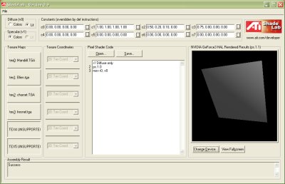
Figure 6 - ATI ShadeLab
You may set up to six textures with specific texture coordinates and the eight constant registers. The main advantage over the MFC Pixel Shader tool is the possibility to load constant registers and the textures on your own. This tool is provided on the Book DVD in the directory [lessthan]Tools>..
With that overview on the available tools in mind, we can go one step further by examining a diagram with the pixel shader workflow.
[size="5"]Pixel Shader Architecture
The following diagram shows the logical pixel shader data workflow. All the grey fields mark functionality specific for ps.1.1 - ps.1.3. The blue field marks functionality that is specific to ps.1.4.
Figure 7 - Pixel Shader logical Data Flow
On the right half of the diagram the pixel shader arithmetic logic unit (ALU) is surrounded by four kinds of registers. The Color Registers stream iterated vertex color data from a vertex shader or a fixed-function vertex pipeline to a pixel shader. The Constant Registers provide constants to the shader, that are loaded by using the SetPixelShaderConstant() function or in the pixel shader with the def instruction. The Temporary Registers rn are able to store temporay data. The r0 register also serves as the Output register of the pixel shader.
The Texture Coordinates can be supplied as part of the vertex format or can be read from certain kind of texture maps. Texture coordinates are full precision and range as well as perspective correct, when used in a pixel shader. There are D3DTSS_* Texture Operations that are not replaced by the pixel shader functionality, they can be used on the up to four (ps.1.1 - ps.1.3) or six textures (ps.1.4). The Texture Stages are holding a reference to the texture data that might be a one-dimensional (for example in a cartoon shader), two-dimensional or three-dimensional texture (volume textures or cube map). Each value in a texture is called a texel. These texels are most commonly used to store color values, but they can contain any kind of data desired including normal vectors for bump maps, shadow values, or general look-up tables.
Sampling occurs, when a texture coordinate is used to address the texel data at a particular location with the help of the Texture Registers. The usage of the texture registers tn differ between the ps.1.1 - ps.1.3 (t0 - t3) and the ps.1.4 (t0 - t5) implementations.
In case of ps.1.1 - ps.1.3 the association between the texture coordinate set and the texture data is a one-to-one mapping, which is not changeable in the pixel shader. Instead this association can be changed by using the oTn registers in a vertex shader or by using the texture stage state flag TSS_TEXCOORDINDEX together with SetTextureStageState(), in case the fixed function pipeline is used.
In ps.1.4, the texture data and the texture coordinate set can be used independent of each other in a pixel shader. The texture stage from which to sample the texture data is determined by the register number rn and the texture coordinate set, that should be used for the texture data is determined by the number of the tn register specified.
Let's take a closer look at the different registers shown in the upper diagram:
TypeNameps.1.1ps.1.2ps.1.3ps.1.4Read/Write CapsConstant Registersc[sub]n[/sub]8888ROTexture Registerst[sub]n[/sub]4446RW / ps.1.4: ROTemporary Registersr[sub]n[/sub]2226RWColor Registersv[sub]n[/sub]2222 in Phase 2RO[size="3"]Constant Registers (c0 - c7)
There are eight constant registers in every pixel shader specification. Every constant register contains four floating point values or channels. They are read-only from the perspective of the pixel shader, so they could be used as a source register, but never as destination registers in the pixel shader. The application can write and read constant registers with calls to SetPixelShaderContant() and GetPixelShaderConstant(). A def instruction used in the pixel shader to load a constant register, is effectively translated into a SetPixelShaderConstant() call by executing SetPixelShader().
The range of the constant registers goes from -1 to +1. If you pass anything outside of this range, it just gets clamped. Constant registers are not usable by ps.1.1 - ps.1.3 texture address instructions except for the texm3x3spec, which uses a constant register to get an eye-ray vector.
Output and Temporary Registers (ps.1.1 - ps.1.3: r0 + r1; ps.1.4: r0 - r5)
The temporary registers r0 - rn are used to store intermediate results. The output register r0 is the destination argument for the pixel shader instruction. So r0 is able to serve as a temporary and output register. In ps.1.4 r0 - r5 are also used to sample texture data from the texture stages 0 - 5 in conjunction with the texture registers. In ps.1.1 - ps.1.3, the temporary registers are not usable by texture address instructions.
CreatePixelShader() will fail in shader pre-processing if a shader attempts to read from a temporary register that has not been written to by a previous instruction. All shaders have to write to r0.rgba the final result or the shader will not assemble or validate.
Texture Registers (ps.1.1 - ps.1.3: t0 - t3; ps.1.4: t0 - t5)
The texture registers are used in different ways in ps.1.1 - ps.1.3 and in ps.1.4. In ps.1.1 - ps.1.3 the usage of one of the t0 - t3 texture registers determine the usage of a specific pair of texture data and texture coordinates. You can't change this one-to-one mapping in the pixel shader:
ps.1.1 // version instruction tex t0 // samples the texture at stage 0 // using texture coordinates from stage 0 mov r0, t0 // copies the color in t0 to output register r0
tex samples the texture data from the texture stage 0 and uses the texture coordinates set, that is set in the vertex shader with the oTn registers. In ps.1.4, having texture coordinates in their own registers means that the texture coordinate set and the texture data are independant from each other. The texture stage number with the texture data from which to sample is determined by the destination register number (r0 - r5) and the texture coordinate set is determined by the source register (t0 - t5) specified in phase 1. ps.1.4 // version instruction texld r4, t5 mov r0, r4
The texld instruction samples the map set via SetTexture (4, lpTexture) using the sixth set of texture coordinates (set in the vertex shader with oT5) and puts the result into the fifth temporary register r4.Texture registers that doesn't hold any values will be sampled to opaque black (0.0, 0.0, 0.0, 1.0). They can be used as temporary registers in ps.1.1 - ps.1.3. The texture coordinate registers in ps.1.4 are read-only and therefore not usable as temporary registers.
The maximum number of textures is the same as the maximum number of simultaneous textures supported (MaxSimultaneousTextures flag in D3D8CAPS).
Color Registers (ps.1.1 - ps.1.4: v0 + v1)
The color registers can contain per-vertex color values in the range 0 through 1 (saturated). It is common to load v0 with the vertex diffuse color and v1 with the specular color.
Using a constant color (flat shading) is more efficient than using an per-pixel Gouraud shaded vertex color. If the shade mode is set to D3DSHADE_FLAT, the application iteration of both vertex colors (diffuse and specular) is disabled. But regardless of the shade mode, fog will still be iterated later in the pipeline.
Pixel shaders have read-only access to color registers. In ps.1.4 color registers are only available during the second phase, which is the default phase. All of the other registers are available in every of the two phases of ps.1.4.Range
One reason for using pixel shaders is compared to the multitexturing unit, its higher precision that is used by the pixel shader arithmetic logic unit.
Register Name Range Versions cn -1 to +1 all versions rn -D3DCAPS8.MaxPixelShaderValue to D3DCAPS8.MaxPixelShaderValue all versions tn -D3DCAPS8.MaxPixelShaderValue to D3DCAPS8.MaxPixelShaderValue ps.1.1 - ps.1.3 -D3DCAPS8.MaxTextureRepeat to D3DCAPS8.MaxTextureRepeat ps.1.4 vn 0 to +1 all versions The color register vn are 8bit precision per channel, ie 8bit red, 8bit green etc.. For ps.1.1 to ps.1.3, D3DCAPS8.MaxPixelShaderValue is a minimum of one, whereas in ps.1.4 D3DCAPS8.MaxPixelShaderValue is a minimum of eight. The texture coordinate registers provided by ps.1.4 use high precision signed interpolators. The DirectX caps viewer reports a MaxTextureRepeat value of 2048 for the RADEON 8500. This value will be clamped to MaxPixelShaderValue, when used with texcrd, because of the usage of a rn register as the destination register. In this case it is safest to stick with source coordinates within the MaxPixelShaderValue range. However, if tn registers are used for straight texture lookups (i.e. texld r0, t3), then the MaxTextureRepeat range should be expected to be honored by hardware.
Using textures to store color values leads to a much higher color precision with ps.1.4.
High Level View on Pixel Shader Programming
Pixel Shading takes place on a per-pixel, per-object basis during a rendering pass.
Let's start by focusing on the steps required to build a pixel shader-driven application. The following list ordered in the sequence of execution shows the necessary steps to build up a pixel shader driven application:
- Check for Pixel Shader Support
- Set Texture Operation Flags (with D3DTSS_* flags)
- Set Texture (with SetTexture())
- Define Constants (with SetPixelShaderConstant()/def)
- Pixel Shader Instructions
- Texture Address Instructions
- Arithmetic Instructions
Check for Pixel Shader Support
It is important to check for the proper pixel shader support, because there is no feasible way to emulate pixel shaders. So in case there is no pixel shader support or the required pixel shader version is not supported, there have to be fallback methods to a default behaviour (ie the multitexturing unit or ps.1.1). The following statement checks the supported pixel shader version:
if( pCaps->PixelShaderVersion < D3DPS_VERSION(1,1) ) return E_FAIL;
This example checks the support of the pixel shader version 1.1. The support of at least ps.1.4 in hardware might be checked with D3DPS_VERSION(1,4). The D3DCAPS structure has to be filled in the startup phase of the application with a call to GetDeviceCaps(). In case the Common Files Framework which is provided with the DirectX 8.1 SDK is used, this is done by the framework. If you graphics card does not support the requested pixel shader version and there is no fallback mechanism that switches to the multitexturing unit, the reference rasterizer will jump in. This is the default behaviour of the Common Files Framework, but it is not useful in a game, because the REF is too slow.Set Texture Operation Flags (D3DTSS_* flags)
The pixel shader functionality replaces the D3DTSS_COLOROP and D3DTSS_ALPHAOP operations and their associated arguments and modifiers that were used with the fixed-function pipeline. For example the following four SetTextureStageState() calls could be handled now by the pixel shader:
m_pd3dDevice->SetTextureStageState( 0, D3DTSS_COLORARG1, D3DTA_TEXTURE ); m_pd3dDevice->SetTextureStageState( 0, D3DTSS_COLORARG2, D3DTA_DIFFUSE); m_pd3dDevice->SetTextureStageState( 0, D3DTSS_COLOROP, D3DTOP_MODULATE); m_pd3dDevice->SetTexture( 0, m_pWallTexture);
But the following texture stage states are still observed. D3DTSS_ADDRESSU D3DTSS_ADDRESSV D3DTSS_ADDRESSW D3DTSS_BUMPENVMAT00 D3DTSS_BUMPENVMAT01 D3DTSS_BUMPENVMAT10 D3DTSS_BUMPENVMAT11 D3DTSS_BORDERCOLOR D3DTSS_MAGFILTER D3DTSS_MINFILTER D3DTSS_MIPFILTER D3DTSS_MIPMAPLODBIAS D3DTSS_MAXMIPLEVEL D3DTSS_MAXANISOTROPY D3DTSS_BUMPENVLSCALE D3DTSS_BUMPENVLOFFSET D3DTSS_TEXCOORDINDEX D3DTSS_TEXTURETRANSFORMFLAGS
The D3DTSS_BUMP* states are used with the bem, texbem and texbeml instructions.In ps.1.1 - ps.1.3 all D3DTSS_TEXTURETRANSFORMFLAGS flags are available and have to be properly set for a projective divide, whereas in ps.1.4 the texture transform flag D3DTTFF_PROJECTED is ignored. It is accomplished by using source register modifiers with the texld and texcrd registers.
The D3DTSS_TEXCOORDINDEX flag is valid only for fixed-function vertex processing. when rendering with vertex shaders, each stages's texture coordinate index must be set to its default value. The default index for each stage is equal to the stage index.
ps.1.4 gives you the ability to change the association of the texture coordinates and the textures in the pixel shader.
The texture wrapping, filtering, color border and mip mapping flags are fully functional in conjunction with pixel shaders.
A change of these texture stage states doesn't require the regeneration of the currently bound shader, because they are not available to shader compile time and the driver can therefore make no assumption about them.
Set Texture (with SetTexture()
After checking the pixel shader support and setting the proper texture operation flags, all textures have to be set by SetTexture(), as with the DX6/7 multitexturing unit. The prototype of this call is:
HRESULT SetTexture(DWORD Stage, IDirect3DBaseTexture8* pTexture);
The texture stage that should be used by the texture is provided in the first parameter and the pointer to the texture interface is provided in the second parameter. A typical call might look like: m_pd3dDevice->SetTexture( 0, m_pWallTexture);
This call sets the already loaded and created wall texture to texture stage 0.Define Constants (with SetPixelShaderConstant() / def)
The constant registers can be filled with SetPixelShaderConstant() or the def instruction in the pixel shader. Similar to the SetVertexShaderConstant() call, the prototype of the pixel shader equivalent looks like this
HRESULT SetPixelShaderConstant( DWORD Register, CONST void* pConstantData, DWORD ConstantCount );
First the constant register must be specified in Register. The data to transfer into the constant register is provided in the second argument as a pointer. The number of constant registers, that have to be filled is provided in the last parameter. For example to fill c0 - c4, you might provide c0 as the Register and 4 as the ConstantCount.The def instruction is an alternative to SetPixelShaderConstant(). When SetPixelShader() is called, it is effectively translated into a SetPixelShaderConstant() call. Using the def instruction makes the pixel shader easier to read. A def instruction in the pixel shader might look like this:
def c0, 0.30, 0.59, 0.11, 1.0
Each value of the constant source registers has to be in the range [-1.0..1.0].Pixel Shader Instructions
Using vertex shaders the programmer is free to choose the order of the used instructions in any way that makes sense, whereas pixel shaders need a specific arrangement of the used instructions. This specific instruction flow differs between ps.1.1 - ps.1.3 and ps.1.4.
ps.1.1 - ps.1.3 allow four types of instructions, that must appear in the order shown below:
Figure 8 - ps.1.1 - ps.1.3 Pixel Shader Instruction Flow
(Specular Lighting with Lookup table)
This example shows a per-pixel specular lighting model, that evaluates the specular power with a lookup table. Every pixel shader starts with the version instruction. It is used by the assembler to validate the instructions which follow. Below the version instruction a constant definition could be placed with def. Such a def instruction is translated into a SetPixelShaderConstant() call, when SetPixelShader() is executed.
The next group of instructions are the so-called texture address instructions. They are used to load data from the tn registers and additionally in ps.1.1 - ps.1.3 to modify texture coordinates. Up to four texture address instructions could be used in a ps.1.1 - ps.1.3 pixel shader.
In this example the tex instruction is used to sample the normal map, that holds the normal data. texm* instructions are always used at least as pairs:
texm3x2pad t1, t0_bx2 texm3x2tex t2, t0_bx2
Both instructions calculate the proper u/v texture coordinate pair with the help of the normal map in t0 and sample the texture data from t2 with it. This texture register holds the light map data with the specular power values. The last texture addressing instruction samples the color map into t3.The next type of instructions are the arithmetic instructions. There could be up to eight arithmetic instructions in a pixel shader.
mad adds t2 and c0, the ambient light, and multiplies the result with t3 and stores it into the output register r0.
Instructions in a ps.1.4 pixel shader must appear in the order shown below:
Figure 9 - ps.1.4 Pixel Shader Instruction Flow
(Simple transfer function for sepia or heat signature effects)
This is a simple transfer function, which could be useful for sepia or heat signature effects. It is explained in detail in [Mitchell]. The ps.1.4 pixel shader instruction flow has to start with the version instruction ps.1.4. After that, as much def instructions as needed might be placed into the pixel shader code. This example sets a Luminance constant value with one def.
There could be up to six texture addressing instructions used after the constants. The texld instruction loads a texture from texture stage 0, with the help of the texture coordinate pair 0, which is chosen by using t0. In the following up to eight arithmetic instructions, color, texture or vector data might be modified. This shader uses only the arithmetic instruction to convert the texture map values to luminance values.
So far a ps.1.4 pixel shader has the same instruction flow like a ps.1.1 - ps.1.3 pixel shader, but the phase instruction allows it to double the number of texture addressing and arithmetic instructions. It divides the pixel shader in two phases: phase 1 and phase 2. That means as of ps.1.4 a second pass through the pixel shader hardware can be done.
Another way to re-use the result of a former pixel shader pass is to render into a texture and use this texture in the next pixel shader pass. This is accomplished by rendering into a seperate render target.
The additional six texture addressing instruction slots after the phase instruction are only used by the texld r5, r0 instruction. This instruction uses the color in r0, which was converted to Luminance values before as a texture coordinate to sample a 1D texture (sepia or heat signature map), which is referenced by r5. The result is moved with a mov instruction into the output register r0.Adding the number of arithmetic and addressing instructions shown in the pixel shader instruction flow above, leads to 28 instructions. If no phase marker is specified, the default phase 2 allows up to 14 addressing and arithmetic instructions.
Both of the preceding examples show the ability to use dependant reads. A dependant read is a read from a texture map using a texture coordinate which was calculated earlier in the pixel shader. More details on dependant reads will be presented in the next section.
Texture Address Instructions
Texture address instructions are used on texture coordinates. The texture coordinate address is used to sample data from a texture map. Controlling the u/v pair, u/v/w triplet or a u/v/w/q quadruplet of texture coordinates with address operations, gives the ability to choose different areas of a texture map. Texture coordinate "data storage space" can also be used for other reasons than sampling texture data. The registers that reference texture coordinate data, are useful to "transport" any kind of data from the vertex shader to the pixel shader via the oTn registers of a vertex shader. For example the light or half-angle vector or a 3x2, 3x3 or a 4x4 matrix might be provided to the pixel shader this way.
ps.1.1 - ps.1.3 texture addressing
The following diagram shows the ways that texture address instructions work in ps.1.1 - ps.1.3 for texture addressing:

Figure 10 - Texture Addressing in ps.1.1 - ps.1.3
All of the texture addressing happens "encapsulated" in the texture address instructions masked with a grey field. That means results of texture coordinate calculations are not accessible in the pixel shader. The texture address instruction uses these results internally to sample the texture. The only way to get access to texture coordinates in the pixel shader is the texcoord instruction. This instruction converts texture coordinate data to color values, so that they can be manipulated by texture addressing or arithmetic instructions. These color values could be used as texture coordinates to sample a texture with the help of the texreg2* instructions.
The following instructions are texture address instructions in ps.1.1 - ps.1.3. The d and s in the column named Para are the destination and source parameters of the instruction. The usage of texture coordinates is shown by two brackets around the texture register, for example (t0).
Instruction 1.1 1.2 1.3 Para Action tex x x x d Loads tn with color data (RGBA) sampled from the texture texbem x x x d, s Transforms red and green components as du, dv signed values of the source register using a 2-D bump mapping matrix, to modify the texture address of the destination register. Can be used for a variety of techniques based on address perturbation such as fake per-pixel environment mapping, diffuse lighting (bump mapping), environment matting etc..
There is a difference in the usage of the texture stages between environment mapping with a pixel shader (means texbem, texbeml or bem) and environment mapping with the DX 6/7 multitexturing unit. texbem (texbeml or bem) needs the matrix data connected to the texture stage that is sampled. This is the environment map. Environment mapping with the DX 6/7 multitexturing unit needs the matrix data connected to the texture stage used by the bump map (see also the example program Earth Bump on the DVD):
------------------ // texture stages for environment mapping // with a pixel shader: SetRenderState(D3DRS_WRAP0,D3DWRAP_U|D3DWRAP_V); // color map SetTexture( 0, m_pEarthTexture ); SetTextureStageState(0, D3DTSS_TEXCOORDINDEX, 1); // bump map SetTexture(1, m_psBumpMap); SetTextureStageState(1, D3DTSS_TEXCOORDINDEX, 1); // enviroment map SetTexture(2, m_pEnvMapTexture); SetTextureStageState(2, D3DTSS_TEXCOORDINDEX, 0); SetTextureStageState(2, D3DTSS_BUMPENVMAT00, F2DW(0.5f)); SetTextureStageState(2, D3DTSS_BUMPENVMAT01, F2DW(0.0f)); SetTextureStageState(2, D3DTSS_BUMPENVMAT10, F2DW(0.0f)); SetTextureStageState(2, D3DTSS_BUMPENVMAT11, F2DW(0.5f)); texbem performs the following operations:
u += 2x2 matrix(du)
v += 2x2 matrix(dv)
Then sample (u, v)
Read more in the section "Bump Mapping Formulas" in the DirectX 8.1 SDK documentation.
Some rules for texbem/texbeml:
The s register can not be read by any arithmetic instruction, until it is overwritten again by another instruction:
... texbem/l t1, t0 mov r0, t0 ; not legal ... texbem/l t1, t0 mov t0, c0 mov r0, t0 ; legal ... The s register of texbem/l can not be read by any texture instruction except for the texbem/l instruction:
... texbem/l t1, t0 texreg2ar t2, t0 ; not legal ... texbem/l t1, t0 texbem/l t2, t0 ; legal ... --------------------------------- ; t2 environment map ; (t2) texture coordinates environment map ; t1 du/dv perturbation data ps.1.1 tex t0 ; color map tex t1 ; bump map texbem t2, t1 ; Perturb and then sample the ; environment map. add r0, t2, t0 See the bem instruction for the ps.1.4 equivalent. See also the chapter on particle flow from Daniel Weiskopf and Matthias Hopf [Weiskopf] for an interesting use of texbem.
texbeml x x x d, s Same as above, applys additionally luminance. Now three components of the source register are used red, green and blue as du, dv and l for luminance.
u += 2x2 matrix(du) v += 2x2 matrix(dv) Then sample (u, v) & apply Luminance. See the texbem/l rules in the texbem section.
-------------------------------- ; t1 holds the color map ; bump matrix set with the ; D3DTSS_BUMPENVMAT* flags ps.1.1 tex t0 ; bump map with du, dv, l data texbeml t1, t0 ; compute u, v ; sample t1 using u, v ; apply luminance correction mov r0, t1 ; output result texcoord x x x d Clamps the texture coordinate to the range [0..1.0] and outputs it as color. If the texture coordinate set contains fewer than three components, the missing components are set to 0. The fourth component is always 1. Provides a way to pass vertex data interpolated at high precision directly into the pixel shader. -------------------------------- ps.1.1 texcoord t0 ; convert texture coordinates ; to color mov r0, t0 ; move color into output ; register r0 texdp3 x x d, s Performs a three-component dot product between the texture coordinate set corresponding to the d register number and the texture data in s and replicate clamped values to all four color channels of d. -------------------------------- ; t0 holds color map ; (t1) hold texture coordinates ps.1.2 tex t0 ; color map texdp3 t1, t0 ; t1 = (t1) dot t0 mov r0, t1 ; output result texdp3tex x x d, s Performs a three-component dot product between the texture coordinate set corresponding to the d register number and the texture data in s. Uses the result to do a 1D texture lookup in d and places the result of the lookup into d. A common application is to lookup into a function table stored in a 1-D texture for procedural specular lighting terms. --------------------------------- ; t1 holds 1D color map ps.1.2 tex t0 ; vector data (x, y, z, w) texdp3tex t1, t0 ; u = (t1) dot t0 ; lookup data in t1 ; result in t1 mov r0, t1 ; output result texkill x x x s Cancels rendering of the current pixel if any of the first three components of the texture coordinates in s is less than zero. When using vertex shaders, the application is responsible for applying the perspective transform. If the arbitrary clipping planes contain anisomorphic scale factors, you have to apply the perspective transform to these clip planes as well. --------------------------------- ps.1.1 texkill t0 ; mask out pixel using ; uvw texture coordinates < 0.0 mov r0, v0 texm3x2depth x d, s Calculates together with a texm3x2pad instruction the depth value to be used in depth testing for this pixel. Performs a three component dot product between the texture coordinate set corresponding to the d register number and the second row of a 3x2 matrix in the s register and stores the resulting w into d. After execution the d register is no longer available for use in the shader.
The benefit of a higher resolution of the depth buffer resulting from multisampling is eliminated, because texm3x2depth (same with ps.1.4: texdepth) will output the single depth value to each of the sub-pixel depth comparison tests.
Needs clamped to [0..1] w and z values or the result stored in the depth buffer will be undefined.
--------------------------------- ; (t1) holds row #1 of the 3x2 matrix ; (t2) holds row #2 of the 3x2 matrix ; t0 holds normal map ps.1.3 tex t0 ; normal map texm3x2pad t1, t0 ; calculates z from row #1 ; calculates w from row #2 ; stores a result in t2 depending on ; if (w == 0) ; t2 = 1.0; ; else ; t2 = z/w; texm3x2depth t2, t0 texm3x2pad x x x d, s This instruction cannot be used by itself. It must be combined with either texm3x2tex or texm3x2depth. It performs a three component dot product between the texture coordinate set corresponding to the d register number and the data of the s register and stores the result in d. See example shown for the texm3x2depth instruction or the example shown for the texm3x2tex instruction.
texm3x2tex x x x d, s It calculates the second row of a 3x2 matrix by performing a three component dot product between the texture coordinate set corresponding to the d register number and the data of the s register to get a v value, which is used to sample a 2D texture. This instruction is used in conjunction with texm3x2pad, that calculates the u value. -------------------------------- ; Dot3 specular lighting with a lookup table ps.1.1 ; t0 holds normal map ; (t1) holds row #1 of the 3x2 matrix (light vector) ; (t2) holds row #2 of the 3x2 matrix (half vector) ; t2 holds a 2D texture (lookup table) ; t3 holds color map tex t0 ; sample normal texm3x2pad t1, t0_bx2 ; calculates u from first row texm3x2tex t2, t0_bx2 ; calculates v from second row ; samples texel with u,v ; from t2 (lookup table) tex t3 ; sample base color mul r0,t2,t3 ; blend terms ------- ; A ps.1.4 equivalent to the ; texm3x2pad/texm3x2tex pair could be ; specular power from a lookup table ps.1.4 ; r0 holds normal map ; t1 holds light vector ; t2 holds half vector ; r2 holds 2D texture (lookup table) ; r3 holds color map texld r0, t0 texcrd r1.rgb, t1 texcrd r4.rgb, t2 dp3 r1.r, r1, r0_bx2 ; calculates u dp3 r1.g, r4, r0_bx2 ; calculates v phase texld r3, t3 texld r2, r1 ; samples texel with u,v ; from r2 (lookup table) mul r0, r2, r3 texm3x3 x x d, s Performs a 3x3 matrix multiply similar to texm3x3tex, except that it does not automatically perform a lookup into a texture. The returned result vector is placed in d with no dependent read. The .a value in d is set to 1.0. The 3x3 matrix is comprised of the texture coordinates of the third texture stage, and by the two preceding texture stages. Any texture assigned to any of the three texture stages is ignored. This instruction must be used with two texm3x3pad instructions.
----------------------------------- ; (t1) holds row #1 of the 3x3 matrix ; (t2) holds row #2 of the 3x3 matrix ; (t3) holds row #3 of the 3x3 matrix ps.1.2 tex t0 ; normal map texm3x3pad t1, t0 ; calculates u from row #1 texm3x3pad t2, t0 ; calculates v from row #2 texm3x3 t3, t0 ; calculates w from row #3 ; store u, v , w in t3 mov r0, t3 ; ps.1.4 equivalent ; r1 holds row #1 of the 3x3 matrix ; r2 holds row #2 of the 3x3 matrix ; r3 holds row #3 of the 3x3 matrix ps.1.4 def c0, 1.0, 1.0, 1.0, 1.0 texld r0, t0 ; r0 normal map texcrd r1.rgb, t1 ; calculates u from row #1 texcrd r2.rgb, t2 ; calculates v from row #2 texcrd r3.rgb, t3 ; calculates w from row #3 dp3 r4.r, r1, r0 dp3 r4.g, r2, r0 dp3 r4.b, r3, r0 ; store u, w, w in r4.rgb mov r0.a, c0 +mov r0.rgb, r4 texm3x3pad x x x d, s Performs the first or second row of a 3x3 matrix multiply. The instruction can not be used by itself and must be used with texm3x3, texm3x3spec, texm3x3vspec or texm3x3tex. texm3x3spec x x x d,s1, s2 Performs together with two texm3x3pad instructions a 3x3 matrix multiply. The resulting vector is used as a normal vector to reflect the eye-ray vector from a constant register in s2 and then uses the reflected vector as a texture address for a texture lookup in d.
The 3x3 matrix is typically useful for orienting a normal vector of the correct tangent space for the surface being rendered. The 3x3 matrix is comprised of the texture coordinates of the third texture stage and the results in the two preceding texture stages. Any texture assigned to the two preceding texture stages is ignored.
This can be used for specular reflection and environment mapping.
--------------------------------------- ; (t1) holds row #1 of the 3x3 matrix ; (t2) holds row #2 of the 3x3 matrix ; (t3) holds row #3 of the 3x3 matrix ; t3 is assigned a cube or volume map with ; color data (RGBA) ; t0 holds a normal map ; c0 holds the eye-ray vector E ps.1.1 tex t0 texm3x3pad t1, t0 ; calculates u from row #1 texm3x3pad t2, t0 ; calculates v from row #2 ; calculates w from row #3 ; reflect u, v and w by the ; eye-ray vector in c0 ; use reflected vector to lookup texture in t3 texm3x3spec t3, t0, c0 mov r0, t3 ; output result ; A similar effect is possible with the following ; ps.1.4 pixel shader. ; The eye vector is stored as a normalized ; vector in a cube map ps.1.4 texld r0, t0 ; Look up normal map. texld r1, t4 ; Eye vector through normalizer cube map texcrd r4.rgb, t1 ; 1st row of environment matrix texcrd r2.rgb, t2 ; 2st row of environment matrix texcrd r3.rgb, t3 ; 3rd row of environment matrix dp3 r4.r, r4, r0_bx2 ; 1st row of matrix multiply dp3 r4.g, r2, r0_bx2 ; 2nd row of matrix multiply dp3 r4.b, r3, r0_bx2 ; 3rd row of matrix multiply dp3 r5, r4, r1_bx2 ; (N.Eye) mov r0, r5 texm3x3tex x x x d, s Performs together with two texm3x3pad instructions a 3x3 matrix multiply and uses the result to lookup the texture in d. The 3x3 matrix is typically useful for orienting a normal vector to the correct tangent space for the surface being rendered. The 3x3 matrix is comprised of the texture coordinates of the third texture stage and the two preceding texture stages. The resulting u, v and w is used to sample the texture in stage 3. Any textures assigned to the preceding textures is ignored.
------------------------------------ ; (t1) holds row #1 of the 3x3 matrix ; (t2) holds row #2 of the 3x3 matrix ; (t3) holds row #3 of the 3x3 matrix ; t3 is assigned a cube or volume map with ; color data (RGBA) ps.1.1 tex t0 ; normal map texm3x3pad t1, t0 ; calculates u from row #1