This is an excerpt from the book, Mastering C++ Game Development written by Mickey Macdonald and published by Packt Publishing. With this book, learn high-end game development with advanced C++ 17 programming techniques.
One of the most common uses for shaders is creating lighting and reflection effects. Lighting effects achieved from the use of shaders help provide a level of polish and detail that every modern game strives for. In this post, we will look at some of the well-known models for creating different surface appearance effects, with examples of shaders you can implement to replicate the discussed lighting effect.
Per-vertex diffuse
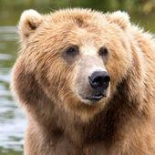
To start with, we will look at one of the simpler lighting vertex shaders, the diffuse reflection shader. Diffuse is considered simple since we assume that the surface we are rendering appears to scatter the light in all directions equally. With this shader, the light makes contact with the surface and slightly penetrates before being cast back out in all directions. This means that some of the light's wavelength will be at least partially absorbed. A good example of what a diffuse shader looks like is to think of matte paint. The surface has a very dull look with no shine.
Let's take a quick look at the mathematical model for a diffuse reflection. This reflection model takes two vectors. One is the direction of the surface contact point to the initial light source, and the second is the normal vector of that same surface contact point. This would look something like the following:
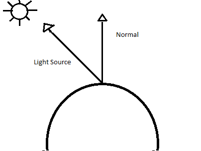
It's worth noting that the amount of light that strikes the surface is partially dependent on the surface in relation to the light source and that the amount of light that reaches a single point will be at its maximum along the normal vector, and its lowest when perpendicular to the normal vector. Dusting off our physics knowledge toolbox, we are able to express this relationship given the amount of light making contact with a point by calculating the dot product of the point normal vector and incoming light vector. This can be expressed by the following formula:
Light Density(Source Vector) Normal Vector
\(LightDensity = Source Vector * Normal Vector\)\(Light Density = SourceVector \cdot NormalVector\)
The source and normal vector in this equation are assumed to be normalized.
As mentioned before, some of the light striking the surface will be absorbed before it is re-cast. To add this behavior to our mathematical model, we can add a reflection coefficient, also referred to as the diffuse reflectivity. This coefficient value becomes the scaling factor for the incoming light. Our new formula to specify the outgoing intensity of the light will now look like the following:
Outgoing Light = (Diffuse Coefficient x Light Density x Source Vector) Normal Vector
\(Outgoing Light = (Diffuse Coefficient x Light Density x Source Vector) \cdot Normal Vector\)
With this new formula, we now have a lighting model that represents an omnidirectional, uniform scattering.
OK, now that we know the theory, let's take a look at how we can implement this lighting model in a GLSL shader. The full source for this example can be found in the Chapter07 folder of the GitHub repository, starting with the Vertex Shader shown as follows:
#version 410
in vec3 vertexPosition_modelspace;
in vec2 vertexUV;
in vec3 vertexNormal;
out vec2 UV;
out vec3 LightIntensity;
uniform vec4 LightPosition;
uniform vec3 DiffuseCoefficient ;
uniform vec3 LightSourceIntensity;
uniform mat4 ModelViewProjection;
uniform mat3 NormalMatrix;
uniform mat4 ModelViewMatrix;
uniform mat4 ProjectionMatrix;

void main()
{
    vec3 tnorm = normalize(NormalMatrix * vertexNormal);
    vec4 CameraCoords = ModelViewMatrix *
    vec4(vertexPosition_modelspace,1.0);

    vec3 IncomingLightDirection = normalize(vec3(LightPosition -
    CameraCoords));
    LightIntensity = LightSourceIntensity * DiffuseCoefficient *
                     max( dot( IncomingLightDirection, tnorm ), 0.0 );

    gl_Position = ModelViewProjection *
                  vec4(vertexPosition_modelspace,1);
                  UV = vertexUV;
 }
We'll go through this shader block by block. To start out, we have our attributes, vertexPosition_modelspace, vertexUV, and vertexNormal. These will be set by our game application, which we will look at after we go through the shader. Then we have our out variables, UV and LightIntensity. These values will be calculated in the shader itself. We then have our uniforms. These include the needed values for our reflection calculation, as we discussed. It also includes all the necessary matrices. Like the attributes, these uniform values will be set via our game.
Inside of the main function of this shader, our diffuse reflection is going to be calculated in the camera relative coordinates. To accomplish this, we first normalize the vertex normal by multiplying it by the normal matrix and storing the results in a vector 3 variable named tnorm.
Next, we convert the vertex position that is currently in model space to camera coordinates by transforming it with the model view matrix. We then calculate the incoming light direction, normalized, by subtracting the vertex position in the camera coordinates from the light's position.
Next, we calculate the outgoing light intensity by using the formula we went through earlier. A point to note here is the use of the max function. This is a situation when the light direction is greater than 90 degrees, as in the light is coming from inside the object. Since in our case we don't need to support this situation, we just use a value of 0.0 when this arises.
To close out the shader, we store the model view projection matrix, calculated in clip space, in the built-in outbound variable gl_position. We also pass along the UV of the texture, unchanged, which we are not actually using in this example.
Now that we have the shader in place, we need to provide the values needed for the calculations. We do this by setting the attributes and uniforms. We built an abstraction layer to help with this process, so let's take a look at how we set these values in our game code. Inside the GamePlayScreen.cpp file, we are setting these values in the Draw() function. I should point out this is for the example, and in a production environment, you would only want to set the changing values in a loop for performance reasons. Since this is an example, I wanted to make it slightly easier to follow:
GLint DiffuseCoefficient = shaderManager.GetUniformLocation("DiffuseCoefficient ");
glUniform3f(DiffuseCoefficient, 0.9f, 0.5f, 0.3f);
GLint LightSourceIntensity = shaderManager.GetUniformLocation("LightSourceIntensity ");
glUniform3f(LightSourceIntensity, 1.0f, 1.0f, 1.0f);
glm::vec4 lightPos = m_camera.GetView() * glm::vec4(5.0f, 5.0f, 2.0f, 1.0f);
GLint lightPosUniform = shaderManager.GetUniformLocation("LightPosition");
glUniform4f(lightPosUniform, lightPos[0], lightPos[1], lightPos[2], lightPos[3]);
glm::mat4 modelView = m_camera.GetView() * glm::mat4(1.0f);

GLint modelViewUniform = shaderManager.GetUniformLocation("ModelViewMatrix");
glUniformMatrix4fv(modelViewUniform, 1, GL_FALSE, &modelView[0][0]);
glm::mat3 normalMatrix = glm::mat3(glm::vec3(modelView[0]),
                         glm::vec3(modelView[1]),
                         glm::vec3(modelView[2]));

GLint normalMatrixUniform = shaderManager.GetUniformLocation("NormalMatrix");
glUniformMatrix3fv(normalMatrixUniform, 1, GL_FALSE, &normalMatrix[0][0]);
glUniformMatrix4fv(MatrixID, 1, GL_FALSE, &m_camera.GetMVPMatrix()[0][0]);
I won't go through each line since I am sure you can see the pattern. We first use the shader manager's GetUniformLocation() method to return the location for the uniform. Next, we set the value for this uniform using the OpenGL glUniform*() method that matches the value type. We do this for all uniform values needed. We also have to set our attributes, and as discussed in the beginning of the chapter, we do this in between the compilation and linking processes. In this example case, we are setting these values in the OnEntry() method of the GamePlayScreen() class:
shaderManager.AddAttribute("vertexPosition_modelspace");
shaderManager.AddAttribute("vertexColor");
shaderManager.AddAttribute("vertexNormal");
That takes care of the vertex shader and passed in values needed, so next, let's look at the fragment shader for this example:
#version 410
in vec2 UV;
in vec3 LightIntensity;

// Ouput data
out vec3 color;

// Values that stay constant for the whole mesh.
uniform sampler2D TextureSampler;

void main()
{
 color = vec3(LightIntensity);
}
For this example, our fragment shader is extremely simple. To begin, we have the in values for our UV and LightIntensity, and we will only use the LightIntensity this time. We then declare our out color value, specified as a vector 3. Next, we have the sampler2D uniform that we use for texturing, but again we won't be using this value in the example. Finally, we have the main function. This is where we set the final output color by simply passing the LightIntensity through to the next stage in the pipeline.
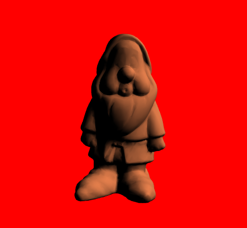
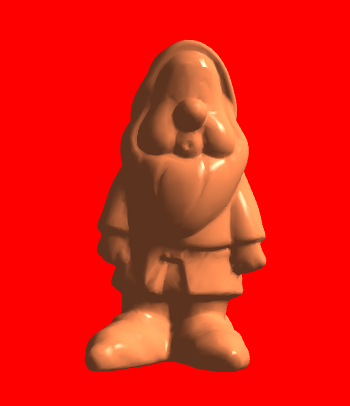
If you run the example project, you will see the diffuse reflection in action. The output should look like the following screenshot. As you can see, this reflection model works well for surfaces that are very dull but has limited use in a practical environment. Next, we will look at a reflection model that will allow us to depict more surface types:
Per-vertex ambient, diffuse, and specular
The ambient, diffuse, and specular (ADS) reflection model, also commonly known as the Phong reflection model, provides a method of creating a reflective lighting shader. This technique models the interaction of light on a surface using a combination of three different components. The ambient component models the light that comes from the environment; this is intended to model what would happen if the light was reflected many times, where it appears as though it is emanating from everywhere. The diffuse component, which we modeled in our previous example, represents an omnidirectional reflection. The last component, the specular component, is meant to represent the reflection in a preferred direction, providing the appearance of a light glare or bright spot.
This combination of components can be visualized using the following diagram:
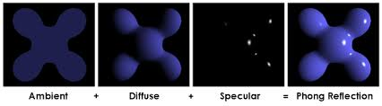
Source: Wikipedia
This process can be broken down into separate components for discussion. First, we have the ambient component that represents the light that will illuminate all of the surfaces equally and reflect uniformly in all directions. This lighting effect does not depend on the incoming or the outgoing vectors of the light since it is uniformly distributed and can be expressed by simply multiplying the light source's intensity with the surface reflectivity. This is shown in the mathematical formula
Ia = LaKa
The next component is the diffuse component we discussed earlier. The diffuse component models a dull or rough surface that scatters light in all directions. Again, this can be expressed with the mathematical formula
Id = LdKd(sn)
The final component is the specular component, and it is used to model the shininess of the surface. This creates a glare or bright spot that is common on surfaces that exhibit glossy properties. We can visualize this reflection effect using the following diagram:
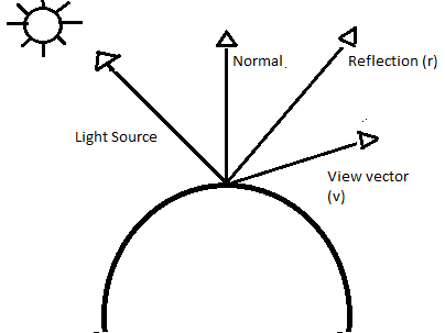
For the specular component, ideally, we would like the reflection to be at is most apparent when viewed aligned with the reflection vector, and then to fade off as the angle is increased or decreased from this alignment. We can model this effect using the cosine of the angle between our viewing vector and the reflection angle, which is then raised by some power, as shown in this equation: (r v) p. In this equation, p represents the specular highlight, the glare spot. The larger the value input for p, the smaller the spot will appear, and the shinier the surface will look. After adding the values to represent the reflectiveness of the surface and the specular light intensity, the formula for calculating the specular effect for the surface looks like so:
Is = LsKs(r v) p
So, now, if we take all of our components and put them together in a formula, we come up with
I = Ia + Id + Is
or breaking it down more,
I = LaKa + LdKd(sn) + LsKs(r v) p
With our theory in place, let's see how we can implement this in a per-vertex shader, beginning with our vertex shader as follows:
#version 410
// Input vertex data, different for all executions of this shader.
in vec3 vertexPosition_modelspace;
in vec2 vertexUV;
in vec3 vertexNormal;

// Output data ; will be interpolated for each fragment.
out vec2 UV;
out vec3 LightIntensity;

struct LightInfo {
 vec4 Position; // Light position in eye coords.
 vec3 La; // Ambient light intensity
 vec3 Ld; // Diffuse light intensity
 vec3 Ls; // Specular light intensity
};

uniform LightInfo Light;
struct MaterialInfo {
 vec3 Ka; // Ambient reflectivity
 vec3 Kd; // Diffuse reflectivity
 vec3 Ks; // Specular reflectivity
 float Shininess; // Specular shininess factor
};

 uniform MaterialInfo Material;
 uniform mat4 ModelViewMatrix;
 uniform mat3 NormalMatrix;
 uniform mat4 ProjectionMatrix;
 uniform mat4 ModelViewProjection;
 void main()
 {
    vec3 tnorm = normalize( NormalMatrix * vertexNormal);
    vec4 CameraCoords = ModelViewMatrix * vec4(vertexPosition_modelspace,1.0);

    vec3 s = normalize(vec3(Light.Position - CameraCoords));
    vec3 v = normalize(-CameraCoords.xyz);
    vec3 r = reflect( -s, tnorm );

    float sDotN = max( dot(s,tnorm), 0.0 );

    vec3 ambient = Light.La * Material.Ka;
    vec3 diffuse = Light.Ld * Material.Kd * sDotN;
    vec3 spec = vec3(0.0);

    if( sDotN > 0.0 )
     spec = Light.Ls * Material.Ks * pow( max( dot(r,v), 0.0 ), Material.Shininess );

    LightIntensity = ambient + diffuse + spec;
    gl_Position = ModelViewProjection * vec4(vertexPosition_modelspace,1.0);
}
Let's take a look at what is different to start with. In this shader, we are introducing a new concept, the uniform struct. We are declaring two struct, one to describe the light, LightInfo, and one to describe the material, MaterialInfo. This is a very useful way of containing values that represent a portion in the formula as a collection. We will see how we can set the values of these struct elements from the game code shortly.
Moving on to the main function of the function. First, we start as we did in the previous example. We calculate the tnorm, CameraCoords, and the light source vector(s). Next, we calculate the vector in the direction of the viewer/camera (v), which is the negative of the normalized CameraCoords. We then calculate the direction of the pure reflection using the provided GLSL method, reflect. Then we move on to calculating the values of our three components.
The ambient is calculated by multiplying the light ambient intensity and the surface's ambient reflective value. The diffuse is calculated using the light intensity, the surface diffuse reflective value of the surface, and the result of the dot product of the light source vector and the tnorm, which we calculated just before the ambient value. Before computing the specular value, we check the value of sDotN. If sDotN is zero, then there is no light reaching the surface, so there is no point in computing the specular component. If sDotN is greater than zero, we compute the specular component.
As in the previous example, we use a GLSL method to limit the range of values of the dot product to between 1 and 0. The GLSL function pow raises the dot product to the power of the surface's shininess exponent, which we defined as p in our shader equation previously.
Finally, we add all three of our component values together and pass their sum to the fragment shader in the form of the out variable, LightIntensity. We end by transforming the vertex position to clip space and passing it off to the next stage by assigning it to the gl_Position variable.
For the setting of the attributes and uniforms needed for our shader, we handle the process just as we did in the previous example. The main difference here is that we need to specify the elements of the struct we are assigning when getting the uniform location. An example would look similar to the following, and again you can see the full code in the example solution in the Chapter07 folder of the GitHub repository:
GLint Kd = shaderManager.GetUniformLocation("Material.Kd");
glUniform3f(Kd, 0.9f, 0.5f, 0.3f);
The fragment shader used for this example is the same as the one we used for the diffuse example, so I won't cover it again here.
When you run the ADS example from the Chapter07 code solution of the GitHub repository, you will see our newly created shader in effect, with an output looking similar to the following:
In this example, we calculated the shading equation within the vertex shader; this is referred to as a per-vertex shader. One issue that can arise from this approach is that our glare spots, the specular highlights, might appear to warp or disappear. This is caused by the shading being interpolated and not calculated for each point across the face. For example, a spot that was set near the middle of the face might not appear due to the fact that the equation was calculated at the vertices where the specular component was near to zero.
You enjoyed an excerpt from the book, Mastering C++ Game Development written by Mickey Macdonald and published by Packt Publishing.
Use the code ORGDB10 at checkout to get recommended eBook retail price for $10 only until May 31, 2018.