We have seen ever-increasing graphics performance in PCs since the release of the first 3dfx Voodoo cards in 1995. Although this performance increase has allowed PCs to run graphics faster, it arguably has not allowed graphics to run much better. The fundamental limitation thus far in PC graphics accelerators has been that they are mostly fixed-function. Fixed-function means that the silicon designers have hard-coded specific graphics algorithms into the graphics chips, and as a result the game and application developers have been limited to using these specific fixed algorithms.
For over a decade, a graphics language known as Photorealistic RenderMan from Pixar Animation Studio has withstood the test of time and has been the choice of professionals for high-quality photo-realistic rendering.
Pixar's use of RenderMan in its development of feature films such as "Toy Story" and "A Bug's Life" has resulted in a level of photorealistic graphics which have amazed audiences worldwide. RenderMan's programmability has allowed it to evolve as major new rendering techniques were invented. By not imposing strict limits on computations, RenderMan allows programmers the utmost in flexibility and creativity. However, this programmability has limited RenderMan to only software implementations.
Now, for the first time, low-cost consumer hardware has reached the point where it can begin implementing the basics of programmable shading similar to the RenderMan graphics language with real-time performance.
The principal 3D APIs (DirectX and OpenGL) have evolved alongside graphics hardware. One of the most important new features in DirectX Graphics is the addition of a programmable pipeline that provides an assembly language interface to the transformation and lighting hardware (vertex shader) and the pixel pipeline (pixel shader). This programmable pipeline gives the developer a lot more freedom to do things, which have never been seen in real time applications before.
Shader programming is the new and real challenge for Game-Coders. Face it ...
[size="5"]What You Are Going To Learn
This introduction covers the fundamentals of Vertex Shader and Pixel Shader Programming. You are going to learn here all the stuff necessary to start programming vertex and pixel shaders for the Windows-family of operating systems from scratch.
We will deal with
- Writing and compiling a vertex shader program
- Lighting with vertex shaders
- Transformation with vertex shaders
- Writing and compiling a pixel shader program
- Texture mapping with the pixel shader
- Texture effects
- Per-pixel lighting with pixel shaders
[size="5"]What You Need to Know/Equipment
You need a basic understanding of the math typically used in a game engine and you need a basic to intermediate understanding of the DirectX Graphics API. It helps if you know how to use the Transform & Lighting (T&L) pipeline and the SetTextureStageState() calls. If you need help with these topics, I recommend working through an introductory level text first. For example "Beginning Direct3D Game Programming" might help :-).
Your development system should consist of the following hardware and software:
- DirectX 8.1 SDK
- Windows 2000 with at least Service Pack 2 or higher or Windows XP Professional (the NVIDIA Shader debugger only runs on these operating systems)
- Visual C/C++ 6.0 with at least Service Pack 5 (needed for the DirectX 8.1 SDK) or higher
- more than 128 MB RAM
- a least 500 MB of hard drive storage
- a hardware accelerated 3D graphics card: To be able to get the maximum visual experience of this course examples, you need to own relatively new graphics hardware. The pixel shader examples will only run properly on GeForce3/4TI or RADEON 8x00 board at the time of this writing
- the NEWEST graphics card device-driver
[size="5"]How This Introduction is Organized
We work through the fundamentals to a more advanced level in four chapters, first for vertex shaders and later for pixel shaders. Our road map looks like this:
- Fundamentals of Vertex Shaders
- Programming Vertex Shaders
- Fundamentals of Pixel Shaders
- Programming Pixel Shaders
[size="5"]Vertex Shaders in the Pipeline
The following diagram shows the Source or Polygon, Vertex and Pixel Operations level of the Direct3D pipeline in a very simplified way:
Figure 1 - Direct3D Pipeline
On the source data level, the vertices are assembled and tessellated. This is the high-order primitive module, which works to tessellate high-order primitives such as N-Patches (as supported by the ATI RADEON 8500 in hardware), quintic B?ziers, B-splines and rectangular and triangular (RT) patches.
A GPU that supports RT-Patches breaks higher-order lines and surfaces into triangles and vertices.
[bquote]It appears that, beginning with the 21.81 drivers, NVIDIA no longer supports RT-patches on the GeForce3/4TI.[/bquote]
A GPU that supports N-Patches generates the control points of a B?zier triangle for each triangle in the input data. This control mesh is based on the positions and normals of the original triangle. The B?zier surface is then tessellated and evaluated, creating more triangles on chip [Vlachos01].[bquote]The N-Patches functionality was enhanced in Direct3D 8.1. There is more control over the interpolation order of the positions and normals of the generated vertices. The new D3DRS_POSITIONORDER and D3DRS_NORMALORDER render states control this interpolation order. The position interpolation order can be set to either D3DORDER_LINEAR or D3DORDER_CUBIC.
The normal interpolation order can be set to either D3DORDER_LINEAR or D3DORDER_QUADRATIC. In Direct3D 8.0, the position interpolation was hard wired to D3DORDER_CUBIC and the normal interpolation was hard wired to D3DORDER_LINEAR.
Note: If you use N-Patches together with programmable vertex shaders, you have to store the position and normal information in input registers v0 and v3. That's because the N-Patch Tesselator needs to know where these informations are to notify the driver.[/bquote]
The next stage shown in Figure 1 covers the vertex operations in the Direct3D pipeline. There are two different ways of processing vertices.The normal interpolation order can be set to either D3DORDER_LINEAR or D3DORDER_QUADRATIC. In Direct3D 8.0, the position interpolation was hard wired to D3DORDER_CUBIC and the normal interpolation was hard wired to D3DORDER_LINEAR.
Note: If you use N-Patches together with programmable vertex shaders, you have to store the position and normal information in input registers v0 and v3. That's because the N-Patch Tesselator needs to know where these informations are to notify the driver.[/bquote]
- The "fixed-function" pipeline. This is the standard Transform & Lighting (T&L) pipeline, where the functionality is essentially fixed. The T&L pipeline can be controlled by setting render states, matrices, and lighting and material parameters.
- Vertex Shaders. This is the new mechanism introduced in DirectX 8. Instead of setting parameters to control the pipeline, you write a vertex shader program that executes on the graphics hardware.
So what are the capabilities and benefits of using Vertex Shaders?
[size="5"]Why use Vertex Shaders?
If you use Vertex Shaders, you bypass the fixed-function pipeline or T&L pipeline. Why would you want to skip them?
Because the hardware of a traditional T&L pipeline doesn't support all of the popular vertex attribute calculations on its own, processing is often job shared between the geometry engine and the CPU. Sometimes, this leads to redundancy.
There is also a lack of freedom. Many of the effects used in games look similar with the hard-wired T&L pipeline. The fixed-function pipeline doesn't give the developer the freedom he need to develop unique and revolutionary graphical effects. The procedural model used with vertex shaders enables a more general syntax for specifying common operations. With the flexibility of the vertex shaders developers are able to perform operations including:
- Procedural Geometry (cloth simulation, soap bubble [Isidoro/Gosslin])
- Advanced Vertex Blending for Skinning and Vertex Morphing (tweening) [Gosselin]
- Texture Generation [Riddle/Zecha]
- Advanced Keyframe Interpolation (complex facial expression and speech)
- Particle System Rendering
- Real-Time Modifications of the Perspective View (lens effects, underwater effect)
- Advanced Lighting Models (often in cooperation with the pixel shader) [Bendel]
- First Steps to Displacement Mapping [Calver]
In addition to opening up creative possibilities for developers and artists, shaders also attack the problem of constrained video memory bandwidth by executing on-chip on shader-capable hardware. Take, for example, B?zier patches. Given two floating point values per vertex (plus a fixed number of values per primitive), one can design a vertex shader to generate a position, a normal and a number of texture coordinates. Vertex Shaders even give you the possibility to decompress compressed position, normal, color, matrix and texture coordinate data and to save a lot of valuable bandwidth without any additional cost [Calver].
And there is also a benefit for your future learning curve. The procedural programming model used by vertex shaders is very scalable. Therefore the adding of new instructions and new registers will happen in a more intuitive way for developers.
[size="5"]Vertex Shader Tools
As you will soon see, you are required to master a specific RISC-oriented assembly language to program vertex shaders, because using the vertex shader is taking responsibility for programming the geometry processor. Therefore, it is important to get the right tools to begin to develop shaders as quickly and productively as possible.
I would like to present the tools that I am aware of at the time of this writing.
[size="3"]NVIDIA Effects Browser 2/3
NVIDIA provides their own DirectX 8 SDK, that encapsulates all their tools, demos and presentations on DirectX 8.0. All the demos use a consistent framework called Effects Browser.
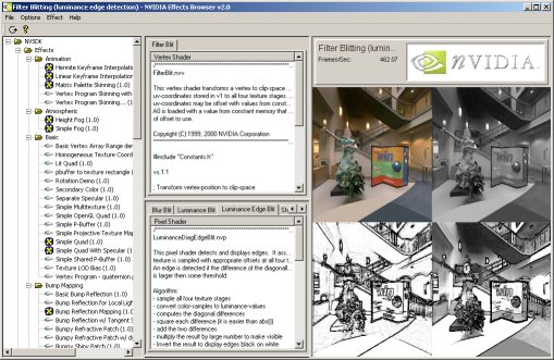
Figure 2 - NVIDIA Effects Browser
The Effects Browser is a wonderful tool to test and develop vertex and pixel shaders. You can select the effect you would like to see in the left column. The middle column gives you the ability to see the source of the vertex and/or pixel shader. The right column displays the effect.
Not all graphics cards will support all the effects available in the Effects Browser. GeForce3/4TI will support all the effects. Independent of your current graphic card preferences, I recommend downloading the NVIDIA DirectX 8 SDK and trying it out. The many examples, including detailed explanations, show you a variety of the effects possible with vertex and pixel shaders. The upcoming NVIDIA EffectsBrowser 3 will provide automatic online update capabilities.
[size="3"]NVIDIA Shader Debugger
Once you have used it, you won't live without it. The NVIDIA shader debugger provides you with information about the current state of the temporary registers, the input streams, the output registers, and the constant memory. This data changes interactively while stepping through the shaders. It is also possible to set instruction breakpoints as well as specific breakpoint.
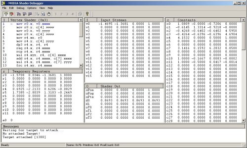
Figure 3- NVIDIA Shader Debugger
A user manual that explains all the possible features is provided. You need at least Windows 2000 with Service Pack 1 to run the Shader Debugger because debug services in DX8 and DX8.1 are only supplied in Windows 2000 and higher. It is important that your application use software vertex processing (or you have switched to the reference rasterizer) in the runtime for the debugging process.
[bquote]You are also able to debug pixel shaders with this debugger, but due to a bug in DirectX 8.0 the contents of t0 are never displayed correctly and user-added pixel shader breakpoints will not trigger. DirectX 8.1 fixes these issues and you receive a warning message if the application finds an installation of DirectX 8.0.[/bquote]
[size="3"]Shader CityYou can find another vertex and pixel shader tool, along with source code at http://www.palevich.com/3d/ShaderCity/. Designed and implemented by Jack Palevich, Shader City allows you to see any modification of the vertex and/or pixel shaders in the small client window in the left upper edge:
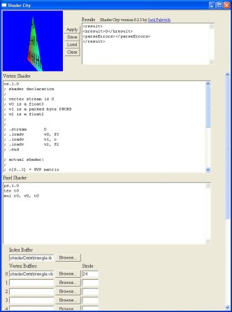
Figure 4 - Jack Palevich Shader City
The results of a modification of a vertex and/or pixel shader can be seen after they are saved and re-loaded. Besides your are able to load index and vertex buffers from a file. The source code for this tool might help you to encapsulate Direct3D in an ActiveX control ... so try it.
[size="3"]Vertex Shader Assembler
To compile a vertex shader ASCII file (for example basic.vsh) into a binary file (for example basic.vso), you must use a vertex shader assembler. As far as I know, there are two vertex shader assemblers: the Microsoft vertex shader assembler and the NVIDIA vertex and pixel shader macro assembler. The latter provides all of the features of the Vertex Shader Assembler plus many other features, whereas the Vertex Shader Assembler gives you the ability to also use the D3DX effect files (as of DirectX 8.1).
NVIDIA NVASM - Vertex and Pixel Shader Macro Assembler
NVIDIA provides its Vertex and Pixel Shader Macro Assembler as part of their DirectX 8 SDK. NVASM has very robust error reporting built into it. It will not only tell you what line the error was on, it is also able to back track errors. Good documentation helps you get started. NVASM was written by ShaderX author Kenneth Hurley, who provides additional information in his ShaderX article [Hurley]. We will learn how to use this tool in one of the upcoming examples in the next chapter.
Microsoft Vertex Shader Assembler
The Microsoft vertex shader assembler is delivered in the DirectX 8.1 SDK in
C:\dxsdk\bin\DXUtils[bquote]Note: The default path of the DirectX 8 SDK is c:\mssdk. The default path of DirectX 8.1 SDK is c:\dxsdk.[/bquote]
If you call vsa.exe from the command line, you will get the following options:usage: vsa -hp012
-h : Generate .h files (instead of .vso files)
-p : Use C preprocessor (VisualC++ required)
-0 : Debug info omitted, no shader validation performed
-1 : Debug info inserted, no shader validation performed
-2 : Debug info inserted, shader validation performed. (default)If you want to be hardware-vendor independent you should use the Microsoft Vertex Shader Assembler.
[size="3"]Shader Studio
ShaderX author John Schwab has developed a tool that will greatly aid in your development of vertex and pixel shaders. Whether you are a beginner or an advanced Direct3D programmer this tool will save you a lot of time, it will allow you to get right down to development of any shader without actually writing any Direct3D code. Therefore you can spend your precious time working on what's important, the shaders.
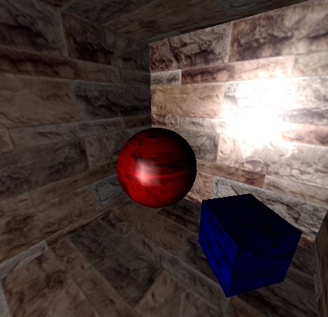
Figure 5 - John Schwab's Shader Studio: Phong Lighting
The tool encapsulates a complete vertex and pixel shader engine with a few nice ideas. For a hand on tutorial and detailed explanations see [Schwab]. The newest version should be available online at www.shaderstudio.com.
[size="3"]NVLink 2.x
NVLink is a very interesting tool, that allows you to:
- Write vertex shaders that consists of "fragments" with #beginfragment and the #endfragment statements. For example:
#beginfragment   world_transform

dp4 r_worldpos.x, v_position, c_world0

dp3 r_worldpos.y, v_position, c_world1

dp4 r_worldpos.z, v_position, c_world2

#endfragment - Assemble vertex shader files with NVASM into "fragments"
- Link those fragments to produce a binary vertex shader at run-time
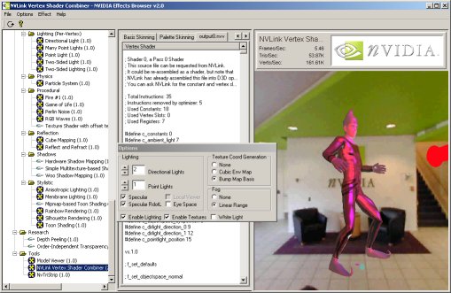
Figure 6 - NVLink
You can choose the vertex shader capabilities in the dialog box and the resulting vertex shader will be shown in output0.nvv in the middle column.
[bquote]Note: the NVLink 2.x example shows the implementation of the fixed-function pipeline in a vertex shader.[/bquote]
[size="3"]NVIDIA Photoshop PlugInsYou will find on NVIDIA's web-site two frequently updated plugin's for Adobe Photoshop. NVIDIA's Normal Map Generator and Photoshop compression plug in. The Normal Map Generator can generate normal maps that can be used, for example, for Dot3 lighting.
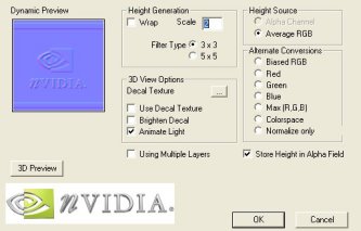
Figure 7 - NVIDIA Normal Map Generator
The plugin requires DirectX 8.0 or later to be installed. The dynamic preview window, located in the upper left corner, shows an example light that is moved with the CTRL + left-mouse-button. You are able to clamp or wrap the edges of the generated normal map by selecting or deselecting the wrap check box. The height values of the normal map can be scaled by providing a height value in the Scale entry field.
There are different options for height generation:
- ALPHA - use alpha channel
- AVERAGE_RGB = average R, G, B
- BIASED_RGB - h = average (R, G, B) - average of whole image
- RED - use red channel
- GREEN - use green channel
- BLUE - use blue channel
- MAX - use max of R, G, B
- COLORSPACE, h = 1.0 - [(1.0 - r) * (1.0 - g) * (1.0 - b)]
Another Adobe Photoshop plugin provided by NVIDIA is the Photoshop Compression Plugin. It is used by choosing in Adobe Photoshop and then the file format. The following dialog provides a wide variety of features:
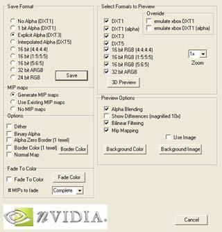
Figure 8 - NVIDIA Compression Plugin
A 3D preview shows the different quality levels that result from different compression formats. This tool can additionally generate mip-maps and convert a height map to a normal map. The provided readme file is very instructive and explains all of the hundreds of features of this tool. As the name implies, both tools support Adobe Photoshop 5.0 and higher.
[size="3"]Diffusion Cubemap Tool
ShaderX author Kenneth Hurley wrote a tool, that helps you producing diffusion cube maps. It aids in extraction of cube maps from digital pictures. The pictures are of a completely reflective ball. The program also allows you to draw an exclusion rectangle to remove the picture taker from the cube map.
To extract the reflection maps first load in the picture and then use the mouse to draw the ellipse enclosed in a rectangle. This rectangle should be stretched and moved so that the ellipse falls on the edges of the ball. Then set which direction is associated with the picture in the menu options. The following screenshots use the Negative X and Negative Z direction:
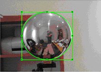
Figure 9 - Negative X Sphere Picture
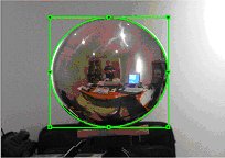
Figure 10 - Negative Z Sphere Picture
The Cube maps are generated with the "Generate" menu option. The program, the source code and much more information can be found at [Hurley].
[size="3"]DLL Detective with Direct3D Plugin
ShaderX author ?d?m Morav?nszky wrote a tool called DLL Detective. It is not only very useful as a performance analysis tool but also for vertex and pixel shader programming:
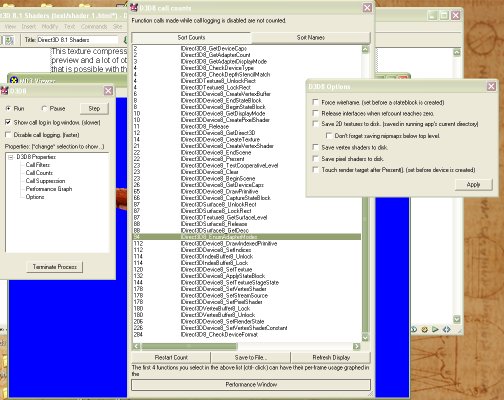
Figure 11 - ?d?m Morav?nszky's DLL Detective
It is able to intercept vertex and pixel shaders, disassemble and write them into a file. A lot of different graphs show the usage of the Direct3D API under different conditions and help to find performance leaks this way. You can even suppress API calls to simulate other conditions. To impede the parallelism of the CPU and GPU usage, you can lock the rendertarget buffer.
DLL Detective is especially suited to instrumenting games, or any other applications which run in fullscreen mode, preventing easy access to other windows (like DLL Detective, for example). To instrument such programs, DLL Detective can be configured to control instrumentation via a multimonitor setup, and even from another PC over a network.
The full source code and compiled binaries can be downloaded from the web-site of the author at http://n.ethz.ch/stu...tive/index.html.
[size="3"]3D Studio MAX 4.x / gmax 1.1
The new 3D Studio MAX 4.x gives a graphic artist the ability to produce vertex shader code and pixel shader code while producing the models and animations.
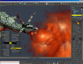
Figure 12 - 3D Studio Max 4.x/gmax 1.1
A WYSIWYG view of your work will appear by displaying multitextures, true transparency, opacity mapping, and the results of custom pixel and vertex shaders.
gmax as a derivative of 3D Studio Max 4.x does support vertex and pixel shader programming. However, the gmax free product provides no user interface to access or edit these controls.
Find more information at discreet.
[size="5"]Vertex Shader Architecture
Let's get deeper into vertex shader programming by looking on a graphical representation of the vertex shader architecture:
Figure 13 - Vertex Shader Architecture
All data are in a vertex shader is represented by 128-bit quad-floats (4 x 32-bit):
Figure 14 - 128 bits
A hardware vertex shader can be seen as a typical SIMD (Single Instruction Multiple Data) processor for you are applying one instruction and affecting a set of up to four 32-bit variables. This data format is very useful, because most of the transformation and lighting calculations are performed using 4x4 matrices or quaternions. The instructions are very simple and easy to understand. The vertex shader does not allow any loops, jumps or conditional branches, which means that it executes the program linearly - one instruction after the other. The maximum length of a vertex shader program in DirectX 8.x is limited to 128 instructions. Combining vertex shaders to have one to compute the transformation and the next one to compute the lighting is impossible. Only one vertex shader can be active at a time and the active vertex shader must compute all required per-vertex output data.
A vertex shader use up to 16 input registers (named v0 - v15, where each register consists of 128 bit (4x32bit) quad-floats) to access vertex input data. The vertex input register can easily hold the data for a typical vertex: its position coordinates, normal, diffuse and specular color, fog coordinate and point size information with space for the coordinates of several textures.
The constant registers (Constant Memory) are loaded by the CPU, before the vertex shader starts executing parameters defined by the programmer. The vertex shader is not able to write to the constant registers. They are used to store parameters such as light position, matrices, procedural data for special animation effects, vertex interpolation data for morphing/key frame interpolation and more. The constants can be applied within the program and they can even be addressed indirectly with the help of the address register a0.x, but only one constant can be used per instruction. If an instruction needs more than one constant, it must be loaded into on e of the temporary registers before it its required. The names of the constant registers are c0 - c95 or in case of the ATI RADEON 8500 c0 - c191.
The temporary Registers consist of 12 registers used to perform intermediate calculations. They can be used to load and store data (read/write). The names of the temporary registers are r0 - r11.
There are up to 13 output registers (Vertex Output), depending on the underlying hardware. The names of the output registers always start with o for output. The Vertex Output is available per rasterizer and your vertex shader program has write-only access to it. The final result is yet another vertex, a vertex transformed to the "homogenous clip space". Here is an overview of all available registers:
Registers:Number of RegistersPropertiesInput (v0 - v15)16RO1Output (o*)GeForce 3/4TI: 9; RADEON 8500: 11WOConstants (c0 - c95)vs.1.1 Specification: 96; RADEON 8500: 192RO1Temporary (r0 - r11)12R1W3Address (a0.x)1 (vs.1.1 and higher)WO (W: only with mov)An identifier of the streaming nature of this vertex shader architecture is the read-only input registers and the write-only output registers.
[size="5"]High Level View on Vertex Shader Programming
Only one vertex shader can be active at a time. It is a good idea to write vertex shaders on a per-task basis. The overhead of switching between different vertex shaders is smaller than for example a texture change. So if an object needs a special form of transformation or lighting it will get the proper shader for this task. Let's build an abstract example:
You are shipwrecked on a foreign planet. Dressed in your regular armor, armed only with a jigsaw, you move through the candle lit cellars. A monster appears and you crouch behind one of those crates one normally find on other planets. While thinking about your destiny as a hero who saves worlds with jigsaws, you start counting the number of vertex shaders for this scene.
There is one for the monster to animate it, light it and perhaps to reflect its environment. Other vertex shaders will be used for the floor, the walls, the crate, the camera, the candlelight and your jigsaw. Perhaps the floor, the walls, the jigsaw and the crate use the same shader, but the candlelight and the camera might each use one of their own. It depends on your design and the power of the underlying graphic hardware.
[bquote]You might also use vertex shaders on a per-object or per-mesh basis. If for example a *.md3 model consists of, let's say, 10 meshes, you can use 10 different vertex shaders, but that might harm your game performance.[/bquote]
Every vertex shader-driven program must run through the following steps:- Check for vertex shader support by checking the D3DCAPS8::VertexShaderVersion field
- Declaration of the vertex shader with the D3DVSD_* macros, to map vertex buffer streams to input registers
- Setting the vertex shader constant registers with SetVertexShaderConstant()
- Compiling previously written vertex shader with D3DXAssembleShader*() (Alternatives: could be pre-compiled using a Shader Assembler)
- Creating a vertex shader handle with CreateVertexShader()
- Setting a vertex shader with SetVertexShader() for a specific object
- Delete a vertex shader with DeleteVertexShader()
It is important to check the installed vertex shader software or hardware implementation of the end-user hardware. If there is a lack of support for specific features, then the application can fallback to a default behavior or give the user a hint, as to what he might do to enable the required features. The following statement checks for support of vertex shader version 1.1:
if( pCaps->VertexShaderVersion < D3DVS_VERSION(1,1) )

return E_FAIL;if( pCaps->VertexShaderVersion < D3DVS_VERSION(1,0) )
return E_FAIL;Supported vertex shader versions are:
Version:Functionality:0.0DirectX 71.0DirectX 8 without address register A01.1DirectX 8 and DirectX 8.1 with one address register A02.0DirectX 9The only difference between the levels 1.0 and 1.1 is the support of the a0 register. The DirectX 8.0 and DirectX 8.1 reference rasterizer and the software emulation delivered by Microsoft and written by Intel and AMD for their respective CPUs support version 1.1. At the time of this writing, only GeForce3/4TI and RADEON 8500-driven boards support version 1.1 in hardware. No known graphics card supports vs.1.0-only at the time of writing, so this is a legacy version.
[size="3"]Vertex Shader Declaration
You must declare a vertex shader before using it. This declaration can be called a static external interface. An example might look like this:
float c[4] = {0.0f,0.5f,1.0f,2.0f};

DWORD dwDecl0[] = {

  D3DVSD_STREAM(0),

  D3DVSD_REG(0, D3DVSDT_FLOAT3 ),    // input register v0

  D3DVSD_REG(5, D3DVSDT_D3DCOLOR ),  // input Register v5

                                 	// set a few constants

  D3DVSD_CONST(0,1),*(DWORD*)&c[0],*(DWORD*)&c[1],*(DWORD*)&c[2],*(DWORD*)&c[3],

  D3DVSD_END()

};[bquote]For example, one data stream could hold positions and normals, while a second held color values and texture coordinates. This also makes switching between single texture rendering and multi texture rendering trivial: just don't enable the stream with the second set of texture coordinates.[/bquote]
You must declare, which input vertex properties or incoming vertex data has to be mapped to which input register. D3DVSD_REG binds a single vertex register to a vertex element/property from the vertex stream. In our example a D3DVSDT_FLOAT3 value should be placed into the first input register and a D3DVSDT_D3DCOLOR color value should be placed in the sixth input register. For example the position data could be processed by the input register 0 (v0) with D3DVSD_REG(0, D3DVSDT_FLOAT3 ) and the normal data could be processed by input register 3 (v3) with D3DVSD_REG(3, D3DVSDT_FLOAT3 ).How a developer maps each input vertex property to a specific input register is only important, if one want to use N-Patches, because the N-Patch Tessellator needs the position data in v0 and the normal data in v3. Otherwise the developer is free to define the mapping as they see fit. For example the position data could be processed by the input register 0 (v0) with D3DVSD_REG(0, D3DVSDT_FLOAT3) and the normal data could be processed by input register 3 (v3) with D3DVSD_REG(3, D3DVSDT_FLOAT3).
[bquote]In contrast the mapping of the vertex data input to specific registers is fixed for the fixed-function pipeline. d3d8types.h holds a list of #defines that predefine the vertex input for the fixed-function pipeline. Specific vertex elements such as position or normal must be placed in specified registers located in the vertex input memory. For example the vertex position is bound by D3DVSDE_POSITION to Register 0, the diffuse color is bound by D3DVSDE_DIFFUSE to Register 5 etc.. Here's the whole list from d3d8types.h:
The second parameter of D3DVSD_REG specifies the dimensionality and arithmetic data type. The following values are defined in d3d8types.h:#define D3DVSDE_POSITION 0
#define D3DVSDE_BLENDWEIGHT 1
#define D3DVSDE_BLENDINDICES 2
#define D3DVSDE_NORMAL 3
#define D3DVSDE_PSIZE 4
#define D3DVSDE_DIFFUSE 5
#define D3DVSDE_SPECULAR 6
#define D3DVSDE_TEXCOORD0 7
#define D3DVSDE_TEXCOORD1 8
#define D3DVSDE_TEXCOORD2 9
#define D3DVSDE_TEXCOORD3 10
#define D3DVSDE_TEXCOORD4 11
#define D3DVSDE_TEXCOORD5 12
#define D3DVSDE_TEXCOORD6 13
#define D3DVSDE_TEXCOORD7 14
#define D3DVSDE_POSITION2 15
#define D3DVSDE_NORMAL2 16[/bquote]// bit declarations for _Type fields
#define D3DVSDT_FLOAT1 0x00 // 1D float expanded to (value, 0., 0., 1.)
#define D3DVSDT_FLOAT2 0x01 // 2D float expanded to (value, value, 0., 1.)
#define D3DVSDT_FLOAT3 0x02 // 3D float expanded to (value, value, value, 1.)
#define D3DVSDT_FLOAT4 0x03 // 4D float
// 4D packed unsigned bytes mapped to 0. to 1. range
// Input is in D3DCOLOR format (ARGB) expanded to (R, G, B, A)
#define D3DVSDT_D3DCOLOR 0x04
#define D3DVSDT_UBYTE4 0x05 // 4D unsigned byte
// 2D signed short expanded to (value, value, 0., 1.)
#define D3DVSDT_SHORT2 0x06
#define D3DVSDT_SHORT4 0x07 // 4D signed short[bquote]Note. GeForce3/4TI doesn't support D3DVSDT_UBYTE4, as indicated by the D3DVTXPCAPS_NO_VSDT_UBYTE4 caps bit.[/bquote]
D3DVSD_CONST loads the constant values into the vertex shader constant memory. The first parameter is the start address of the constant array to begin filling data. Possible values range from 0 to 95 or in case of the RADEON 8500 from 0 - 191. We start at address 0. The second number is the number of constant vectors (quad-float) to load. One vector is 128 bit long, so we load four 32-bit FLOATs at once. If you want to load a 4x4 matrix, you would use the following statement to load four 128-bit quad-floats into the constant registers c0 - c3:float c[16] = (0.0f, 0.5f, 1.0f, 2.0f,
0.0f, 0.5f, 1.0f, 2.0f,
0.0f, 0.5f, 1.0f, 2.0f,
0.0f, 0.5f, 1.0f, 2.0f);
D3DVSD_CONST(0, 4), *(DWORD*)&c[0],*(DWORD*)&c[1],*(DWORD*)&c[2],*(DWORD*)&c[3],
*(DWORD*)&c[4],*(DWORD*)&c[5],*(DWORD*)&c[6],*(DWORD*)&c[7],
*(DWORD*)&c[8],*(DWORD*)&c[9],*(DWORD*)&c[10],*(DWORD*)&c[11],
*(DWORD*)&c[12],*(DWORD*)&c[13],*(DWORD*)&c[14],*(DWORD*)&c[15],Another example can be:
float	c[4] = {0.0f,0.5f,1.0f,2.0f};

DWORD dwDecl[] = {

  D3DVSD_STREAM(0),

  D3DVSD_REG(0, D3DVSDT_FLOAT3 ), //input register v0

  D3DVSD_REG(3, D3DVSDT_FLOAT3 ), // input register v3

  D3DVSD_REG(5, D3DVSDT_D3DCOLOR ), // input register v5

  D3DVSD_REG(7, D3DVSDT_FLOAT2 ), // input register v7

  D3DVSD_CONST(0,1),*(DWORD*)&c[0],*(DWORD*)&c[1],*(DWORD*)&c[2],*(DWORD*)&c[3],

  D3DVSD_END()

};[size="3"]Setting the Vertex Shader Constant Registers
You will fill the vertex shader constant registers with SetVertexShaderConstant() and get the values from this registers with GetVertexShaderConstant():
// Set the vertex shader constants

m_pd3dDevice->SetVertexShaderConstant( 0, &vZero, 1 );

m_pd3dDevice->SetVertexShaderConstant( 1, &vOne, 1 );

m_pd3dDevice->SetVertexShaderConstant( 2, &vWeight, 1 );

m_pd3dDevice->SetVertexShaderConstant( 4, &matTranspose, 4 );

m_pd3dDevice->SetVertexShaderConstant( 8, &matCameraTranspose, 4 );

m_pd3dDevice->SetVertexShaderConstant( 12, &matViewTranspose, 4 );

m_pd3dDevice->SetVertexShaderConstant( 20, &fLight, 1 );

m_pd3dDevice->SetVertexShaderConstant( 21, &fDiffuse, 1 );

m_pd3dDevice->SetVertexShaderConstant( 22, &fAmbient, 1 );

m_pd3dDevice->SetVertexShaderConstant( 23, &fFog, 1 );

m_pd3dDevice->SetVertexShaderConstant( 24, &fCaustics, 1 );

m_pd3dDevice->SetVertexShaderConstant( 28, &matProjTranspose, 4 );HRESULT SetVertexShaderConstant(
DWORD Register,
CONST void* pConstantData,
DWORD ConstantCount);[bquote]So what's the difference between D3DVSD_CONST used in the vertex shader declaration and SetVertexShaderConstant() ? D3DVSD_CONST can be used only once. SetVertexShaderConstant() can be used before every DrawPrimitive*() call.[/bquote]
Ok ... now we have learned how to check the supported version number of the vertex shader hardware, how to declare a vertex shader and how to set the constants in the constant registers of a vertex shader unit. Next we shall learn, how to write and compile a vertex shader program.[size="3"]Writing and Compiling a Vertex Shader
Before we are able to compile a vertex shader, we must write one ... (old wisdom :-) ). I would like to give you a high-level overview of the instruction set first and then give further details of vertex shader programming in the next chapter named "Programming Vertex Shaders".
The syntax for every instruction is
OpName dest, [-]s1 [,[-]s2 [,[-]s3]] ;comment

e.g.

mov r1, r2

mad r1, r2, -r3, r4 ; contents of r3 are negatedInstructionParametersActionadddest, src1, src2add src1 to src2 (and the optional negation creates substraction)dp3dest, src1, src2three-component dot product
dest.x = dest.y = dest.z = dest.w =
(src1.x * src2.x) + (src1.y * src2.y) + (src1.z * src2.z)dp4dest, src1, src2four-component dot product
dest.w = (src1.x * src2.x) + (src1.y * src2.y) + (src1.z * src2.z) + (src1.w * src2.w);
dest.x = dest.y = dest.z = unused
What is the difference between dp4 and mul ? dp4 produces a scalar product and mul is a component by component vector product.
dstdest, src1, src2The dst instruction works like this: The first source operand (src1) is assumed to be the vector (ignored, d*d, d*d, ignored) and the second source operand (src2) is assumed to be the vector (ignored, 1/d, ignored, 1/d).
Calculate distance vector:
dest.x = 1;
dest.y = src1.y * src2.y
dest.z = src1.z
dest.w = src2.w
dst is useful to calculate standard attenuation. Here is a code snippet that might calculate the attenuation for a point light:
; r7.w = distance * distance = (x*x) + (y*y) + (z*z)

      dp3 r7.w, VECTOR_VERTEXTOLIGHT, VECTOR_VERTEXTOLIGHT

      ; VECTOR_VERTEXTOLIGHT.w = 1/sqrt(r7.w)

      ; = 1/||V|| = 1/distance

      rsq VECTOR_VERTEXTOLIGHT.w, r7.w

      ...

      ; Get the attenuation

      ; d = distance

      ; Parameters for dst:

      ; src1 = (ignored, d * d, d * d, ignored)

      ; src2 = (ignored, 1/d, ignored, 1/d)

      ;

      ; r7.w = d * d

      ; VECTOR_VERTEXTOLIGHT.w = 1/d

      dst r7, r7.wwww, VECTOR_VERTEXTOLIGHT.wwww

      ; dest.x = 1

      ; dest.y = src0.y * src1.y

      ; dest.z = src0.z

      ; dest.w = src1.w

      ; r7(1, d * d * 1 / d, d * d, 1/d)

      ; c[LIGHT_ATTENUATION].x = a0

      ; c[LIGHT_ATTENUATION].y = a1

      ; c[LIGHT_ATTENUATION].z = a2

      ; (a0 + a1*d + a2* (d * d))

      dp3 r7.w, r7, c[LIGHT_ATTENUATION]

      ; 1 / (a0 + a1*d + a2* (d * d))

      rcp ATTENUATION.w, r7.w

      ...

      ; Scale the light factors by the attenuation

      mul r6, r5, ATTENUATION.w
exppdest, src.wExponential 10-bit precision
------------------------------------------
float w = src.w;
float v = (float)floor(src.w);
dest.x = (float)pow(2, v);
dest.y = w - v;
// Reduced precision exponent
float tmp = (float)pow(2, w);
DWORD tmpd = *(DWORD*)&tmp & 0xffffff00;
dest.z = *(float*)&tmpd
dest.w = 1;
--------------------------------------------
Shortcut:
dest.x = 2 **(int) src.w
dest.y = mantissa(src.w)
dest.z = expp(src.w)
dest.w = 1.0litdest, srcCalculates lighting coefficients from two dot products and a power. ---------------------------------------------
To calculate the lighting coefficients, set up the registers as shown:
src.x = N*L ; The dot product between normal and direction to light
src.y = N*H ; The dot product between normal and half vector
src.z = ignored ; This value is ignored
src.w = specular power ; The value must be between -128.0 and 128.0
----------------------------------------------
usage:
dp3 r0.x, rn, c[LIGHT_POSITION]

      dp3 r0.y, rn, c[LIGHT_HALF_ANGLE]

      mov r0.w, c[SPECULAR_POWER]

      lit r0, r0

      ------------------------------------------------

      dest.x = 1.0;

      dest.y = max (src.x, 0.0, 0.0);

      dest.z= 0.0;

      if (src.x > 0.0 && src.w == 0.0)

        dest.z = 1.0;

      else if (src.x > 0.0 && src.y > 0.0)

        dest.z = (src.y)src.w

      dest.w = 1.0;
logpdest, src.wLogarithm 10-bit precision
---------------------------------------------------
float v = ABSF(src.w);
if (v != 0)
{
int p = (int)(*(DWORD*)&v >> 23) - 127;
dest.x = (float)p; // exponent
p = (*(DWORD*)&v & 0x7FFFFF) | 0x3f800000;
dest.y = *(float*)&p // mantissa;
float tmp = (float)(log(v)/log(2));
DWORD tmpd = *(DWORD*)&tmp & 0xffffff00;
dest.z = *(float*)&tmpd
dest.w = 1;
}
else
{
dest.x = MINUS_MAX();
dest.y = 1.0f;
dest.z = MINUS_MAX();
dest.w = 1.0f;
}
-----------------------------------------------------
Sortcut:
dest.x = exponent((int)src.w)
dest.y = mantissa(src.w)
dest.z = log2(src.w)
dest.w = 1.0maddest, src1, src2, src3dest = (src1 * src2) + src3maxdest, src1, src2 dest = (src1 >= src2)?src1:src2mindest, src1, src2 dest = (src1 < src2)?src1:src2movdest, srcmoveOptimization tip: question every use of mov (try to rap that !), because there might be methods that perform the desired operation directly from the source register or accept the required output register as the destination.
muldest, src1, src2 set dest to the component by component product of src1 and src2
; To calculate the Cross Product (r5 = r7 X r8),

      ; r0 used as a temp

      mul r0,-r7.zxyw,r8.yzxw

      mad r5,-r7.yzxw,r8.zxyw,-r0
nop do nothingrcpdest, src.wif(src.w == 1.0f)
{
dest.x = dest.y = dest.z = dest.w = 1.0f;
}
else if(src.w == 0)
{
dest.x = dest.y = dest.z = dest.w = PLUS_INFINITY();
}
else
{
dest.x = dest.y = dest.z = m_dest.w = 1.0f/src.w;
}
Division:
; scalar r0.x = r1.x/r2.x
RCP r0.x, r2.x
MUL r0.x, r1.x, r0.xrsqdest, srcreciprocal square root of src(much more useful than straight 'square root'):
float v = ABSF(src.w);

if(v == 1.0f)

{

  dest.x = dest.y = dest.z = dest.w = 1.0f;

}

else if(v == 0)

{

  dest.x = dest.y = dest.z = dest.w = PLUS_INFINITY();

}

else

{

  v = (float)(1.0f / sqrt(v));

  dest.x = dest.y = dest.z = dest.w = v;

}


Square root:

; scalar r0.x = sqrt(r1.x)

RSQ r0.x, r1.x

MUL r0.x, r0.x, r1.x
sgedest, src1, src2 dest = (src1 >=src2) ? 1 : 0
useful to mimic conditional statements:
; compute r0 = (r1 >= r2) ? r3 : r4

      ; one if (r1 >= r2) holds, zero otherwise

      SGE r0, r1, r2

      ADD r1, r3, -r4

      ; r0 = r0*(r3-r4) + r4 = r0*r3 + (1-r0)*r4

      ; effectively, LERP between extremes of r3 and r4

      MAD r0, r0, r1, r4
sltdest, src1, src2 dest = (src1 < src2) ? 1 : 0You can download this list as a word file from www.shaderx.com. Check out the SDK for additional information.
The Vertex Shader ALU is a multi-threaded vector processor that operates on quad-float data. It consists of two functional units. The SIMD Vector Unit is responsible for the mov, mul, add, mad, dp3, dp4, dst, min, max, slt and sge instructions. The Special Function Unit is responsible for the rcp, rsq, log, exp and lit instructions. Most of these instructions take one cycle to execute, rcp and rsq take more than one cycle under specific circumstances. They take only one slot in the vertex shader, but they actually take longer then one cycle to execute, when the result is used immediately, because that leads to a register stall.
Application Hints
rsq is, for example, used in normalizing vectors to be used in lighting equations. The exponential instruction expp can be used for fog effects, procedural noise generation (see NVIDIA Perlin Noise example), behavior of particles in a particle system (see NVIDIA Particle System example) or to implement a system how objects in a game are damaged. You will use it in any case when a fast changing function is necessary. This is contrary of the use of logarithm functions with logp, that are useful if an extremely slow growing is necessary (also they grow at the beginning pretty fast). A log function can be the inverse of a exponential function, means it undoes the operation of the exponential function.
The lit instruction deals by default with directional lights. It calculates the diffuse & specular factors with clamping based on N * L and N * H and the specular power. There is no attenuation involved, but you can use an attenuation level separately with the result of lit by using the dst instruction. This is useful for constructing attenuation factors for point and spot lights.
The min and max instructions allow for clamping and absolute value computation.
Complex Instructions in the Vertex Shader
There are also complex instructions, that are supported by the vertex shader. The term "macro" should not be used to refer to these instructions, because they are not simply substituted like a C-preprocessor macro. You should think carefully before using these instructions. If you use them, you might lose control over your 128-instruction limit and possible optimization path(s). On the other hand, the software emulation mode provided by Intel or by AMD for their processors is able to optimize a m4x4 complex instruction (and perhaps others now or in the future). It is also possible that, in the future some graphics hardware may use gate count to optimize the m4x4. So, if you need, for example four dp4 calls in your vertex shader assembly source, it might be a good idea to replace them by m4x4. If you have decided to use for example a m4x4 instruction in your shader, you should not use a dp4 call on the same data later, because there are slightly different transformation results. If, for example, both instructions are used for position calculation, z-fighting could result:
MacroParametersActionClocksexppdest, src1provides exponential with full precision to at least 1/2[sup]20[/sup]12frcdest, src1returns fractional portion of each input component3logdest, src1provides log2(x) with full float precision of at least 1/2[sup]20[/sup] 12m3x2dest, src1, src2computes the product of the input vector and a 3x2 matrix2m3x3dest, src1, src2computes the product of the input vector and a 3x3 matrix3m3x4dest, src1, src2computes the product of the input vector and a 3x4 matrix4m4x3dest, src1, src2computes the product of the input vector and a 4x3 matrix3m4x4dest, src1, src2computes the product of the input vector and a 4x4 matrix4You are able to perform all transform and lighting operations with these instructions. If it seems to you that some instructions are missing, rest assured that you can achieve them through the existing instructions for example, the division of two numbers can be realized with a reciprocal and a multiply. You can even implement the whole fixed-function pipeline by using these instructions in a vertex shader. This is shown in the NVLink example of NVIDIA.
Putting it All Together
Now let's see how these registers and instructions are typically used in the vertex shader ALU.
In vs.1.1 there are 16 input registers, 96 constant registers, 12 temporary registers, 1 address register and up to 13 output registers per rasterizer. Each register can handle 4x32-bit values. Each 32-bit value is accessible via an x, y, z and w subscript. That is, a 128-bit value consists of a x, y, z and w value. To access these register components, you must add .x, .y, .z and .w at the end of the register name. Let's start with the input registers:
Using the Input Registers
The 16 input registers can be accessed by using their names v0 to v15. Typical values provided to the input vertex registers are:
- Position(x,y,z,w)
- Diffuse color (r,g,b,a) -> 0.0 to +1.0
- Specular color (r,g,b,a) -> 0.0 to +1.0
- Up to 8 Texture coordinates (each as s, t, r, q or u, v , w, q) but normally 4 or 6, dependent on hardware support
- Fog (f,*,*,*) -> value used in fog equation
- Point size (p,*,*,*)
dp4 oPos.x , v0 , c0

dp4 oPos.y , v0 , c1

dp4 oPos.z , v0 , c2

dp4 oPos.w , v0 , c3oPos.x = (v0.x * c0.x) + (v0.y * c0.y) + (v0.z * c0.z) + (v0.w * c0.w)m4x4 oPos, v0 , c0[bquote]All data in an input register remains persistent throughout the vertex shader execution and even longer. That means they retain their data longer than the life-time of a vertex shader. So it is possible to re-use the data of the input registers in the next vertex shader.[/bquote]
Using the Constant RegistersTypical uses for the constant registers include:
- Matrix data: quad-floats are typically one row of a 4x4 matrix
- Light characteristics, (position, attenuation etc)
- Current time
- Vertex interpolation data
- Procedural data
The constant registers are read-only from the perspective of the vertex shader, whereas the application can read and write into the constant registers. The constant registers retain their data longer than the life-time of a vertex shader so it is possible to re-use this data in the next vertex shader. This allows an app to avoid making redundant SetVertexShaderConstant()