Continuing Summary
After laying down the framework of the editor as described in previous entries, I took on the task of adding the ability to select mesh vertices, faces, and edges. Picking those elements of a static mesh with a mouse click, in a more traditional approach, requires unprojecting the mouse position, and iterating though mesh data, checking for intersections between that mesh world mouse "ray" and the various elements of the mesh. Faces aren't too bad, but the intersection test requires implementation of a ray-triangle intersection test. Vertices aren't horribly bad, either, but still requires choosing an appropriately sized epsilon around each vertex position with which to test the ray intersection. In addition, those tests often include comparing the depth or distance of a hit in order to select the element closest to the eye or camera position in the current view.
Picking elements in a skeletal animated skinned mesh, where vertex positions must be calculated (e.g., from weighted bone animation matrices) before the intersection tests are made, gets even more complex. Debugging the whole algorithm (if you make mistakes as often as I do) can be a very lengthy process.
In addition, even with broad-phase culling for the intersection tests, that algorithm requires testing (in some way) every element in the mesh (thousands of vertices or faces) for every mouse click. The time required for that testing isn't normally a big deal in an editor, where the app spends most of its time waiting for user input. Nevertheless, the process is lengthy and complex - and, as it turns out, is unneeded if a graphical approach to picking is implemented.
In D3D11 (or most other graphics interfaces), skinned meshes are commonly rendered using shaders, and all those vertex bone-weighted calculations are done in the GPU. So, one might ask - if all those calcs are already being done to render the mesh, can that information be used to eliminate or reduce the need for doing similar calcs in the CPU for picking?
The PPP Approach ( Described Yet Again )
The answer to that question is emphatically YES. Consider inverting the traditional picking process - project all the mesh elements into screen space, rather than unprojecting the mouse position into mesh space - and search for mesh elements at the exact screen position of the mouse click. If that were done on the CPU side, it would be considered an inefficient approach. I.e., why convert thousands of vertex positions to screen space to compare to the mouse position, when the mouse position can be converted more efficiently into mesh space for the intersection tests?
However, projecting all the mesh elements into screen space is precisely what the shader does in the rendering process. If that information is captured and used, the picking process becomes much less complex and comprises looking at data at a single pixel position to determine an intersection hit.
As mentioned before, the concept of picking in a pixel-perfect way comes from the mind of gamedev member unbird - a shader wizard. Because I'm basically lazy, I came up with the acronym PPP (Pixel-Perfect Picking) to making typing easier.
PPP takes advantage of several features of HLSL and the D3D11 API:
- Multiple render targets can be written to simultaneously.
- System-value semantics in HLSL such as SV_VertexID and SV_PrimitiveID
Briefly:
1. The user clicks the mouse to select a mesh element (vertex, face, edge), dependent on the current edit mode.
2. A second rendertarget is set before the next frame is rendered.
3. Vertex, geometry and pixel shaders are set to collect and record data in that second rendertarget.
4. The mesh is rendered.
5. The pixel shader returns data in the second rendertarget comprising (e.g.) meshID, faceID, vertexID, etc.
6. The single texel at the screen position of the mouse click in the second rendertarget is examined to determine which mesh element data was last written to that texel.
Keep In Mind ... A mesh may have several vertices with the same position, but different normals, colors, tex coordinates, bone indices/weights, etc. Yes, it's possible to eliminate duplicate vertex positions by using several buffers (position, normal, tex coords, bone weights, etc.) and stream them to the vertex shader. However, I don't do that. So this editor has to account for multiple vertices (different vertex IDs) at the same position.
So ... N.B. the wording in step 6 above. If, for instance, the mesh has multiple vertices with the same position, and because depth testing takes place after the pixel shader returns target data, the data written to the second rendertarget is only for the first vertex at a texel position at the smallest depth. That is, when a second vertex at the same position is rendered, depth testing will discard the data for all rendertargets at that pixel position.
The result of the PPP process is thus limited to determining that at least one element was rendered at the screen position. Data for that particular element can, of course, be read from the second rendertarget data, but other elements at the same depth, at that position, have to be checked.
Picking Edges
Selecting an edge in a skinned mesh with skeletal animation is a whole different ballgame than vertex and face selection.
1. The visual representation of an edge (a line) may be only 1 or 2 pixels in width. For convenience, I want to let the user click near the rendered line without having to click on it in a "pixel perfect" manner.
2. Most edges in an indexed mesh are shared by adjacent triangles. As a result, most edges are drawn twice. The first edge is rendered normally. Other draws of that edge are thrown away during depth testing.
3. For editing purposes, when the user clicks near a line, all coincident edges should be selected.
The following information is needed to pick edges:
1. An indication of an edge near the mouse position where the user clicked to select edges.
2. Information on all edges which are coincident with the edge that's picked.
For the first piece of data, the PPP rendertarget can be used in a way similar to the way vertices and faces are picked. As noted, the PPP rendertarget only records the edge information at a pixel for the last edge that survived the depth test.
Similar to vertex picking discussed in a previous blog, information on all edges coincident with the picked edge is needed. For vertex picking, a geometry shader was used to stream out vertex data. The stream-out buffer data was examined to determine all the vertices coincident with the picked vertex. The geometry shader stream-out approach can't be used for edges because an edge is drawn over a range of pixel positions - from one vertex of a triangle to the next vertex. The geometry shader would "knows" only the individual vertex positions - not the positions between them.
For edge picking, the following scenario is implemented.
On a user mouse click to select an edge, for one render frame, do the following -
1. Construct a pick rectangle - provide an area around the mouse position. Record data for any edges traversing that rectangle, whether they pass the depth test or not.
2. If a pixel for an edge is rendered within the pick rectangle, output meshID, faceID, and edgeID to a second PPP rendertarget.
3. In addition, output meshID, faceID, and edgeID to an ordered access view (UAV) to provide a list of all edges traversing the pick rectangle, whether rendered or not.
FYI - thankfully, data written to a UAV in the pixel shader persists whether the pixel is later clipped or discarded.
The UAV is a uint4 buffer, used to store mesh ID, face ID, edge ID, and a flag to indicate data was written. Initially, the intent was to store data for the entire model. That is, assuming a maximum of 4 meshes per model, the UAV would be sized for 4 * max-num-faces-in-any-mesh * 3. However, because that limits edge picking to 4 meshes per model, a simpler approach of rendering one mesh at a time was implemented. So, current, the UAV is sized for edges in a single mesh - i.e., number-faces * 3, and the pixel shader writes data to the UAV indexed by faceID * 3 + edgeID.
Before describing the edge picking process, here's the geometry shader.
[maxvertexcount(6)]void GS_Edges(triangle GS_INPUT input[3], uint faceID: SV_PrimitiveID, inout LineStream edges){ PS_INPUT output = (PS_INPUT)0; output.Info[1] = faceID; output.Info[3] = 123; // output 3 edges v0-v1, v1-v2, v2-v1 // edge 0 output.Info[2] = 0; output.Pos = input[0].Pos; output.Color = input[0].Color; output.Tex = input[0].Tex; edges.Append(output); output.Pos = input[1].Pos; output.Color = input[1].Color; output.Tex = input[1].Tex; edges.Append(output); // edge 1 output.Info[2] = 1; output.Pos = input[1].Pos; output.Color = input[0].Color; output.Tex = input[1].Tex; edges.Append(output); output.Pos = input[2].Pos; output.Color = input[2].Color; output.Tex = input[2].Tex; edges.Append(output); // edge 2 output.Info[2] = 2; output.Pos = input[2].Pos; output.Color = input[2].Color; output.Tex = input[2].Tex; edges.Append(output); output.Pos = input[0].Pos; output.Color = input[0].Color; output.Tex = input[0].Tex; edges.Append(output); edges.RestartStrip();}The pixel shader outputs the data to the second (PPP) rendertarget. It also tests if the position is within the pick rectangle. If so, the same data is output to the UAV.
RWBuffer SelEdgeInfo : register(u2); // 2 rendertargets and a UAVstruct PS_OUTPUT{ float4 Color : SV_Target0; uint4 Info : SV_Target1;};// use the pixel shader to pick edge information within the rect specified// input.Info = 0->meshID, 1->faceID, 2->edge number, 3 = 123 flagPS_OUTPUT PS_UAV(PS_INPUT input){ PS_OUTPUT output = (PS_OUTPUT)0; output.Color = input.Color; input.Info[0] = (uint)bLighting.z; // meshNum output.Info = input.Info; // pickInfo is a uint4 in a constant buffer with the coords fro the pick rectangle in screen coords if (input.Pos.x >= pickInfo[0] && input.Pos.x <= pickInfo[2] && input.Pos.y >= pickInfo[1] && input.Pos.y <= pickInfo[3]) SelEdgeInfo[input.Info[1] * 3 + input.Info[2]] = input.Info; return output;}The end result following that process is:
1. The second rendertarget which now holds data at each pixel position where an edge traversed. As noted above, that data is actually for the edge that last passed the depth test.
2. A UAV buffer which holds data for any edge that traversed the pick rectangle.
The pick rectangle in the PPP rendertarget is analysed to determine what edge traversed closest to the pick position (center of the rectangle). Taking a comment (first comment in that link) Ashaman73 made regarding weighting pixels, each pixel position which contains data is weighted by its distance from the pick position. The data at the highest weighted position is the "selected" edge - i.e., mesh ID, face ID and edge ID.
Using that edge identification, the UAV buffer is examined for all edges which traversed the pick rectangle. The mesh data for those edges is examined to determine which are coincident with the "selected" edge - i.e., which edges are defined by vertices that are within a small epsilon of the vertices that define the "selected" edge. Those matching edges from the UAV, and the edge selected in the PPP rendertarget are all added to the model's "selected edge" std::vector.
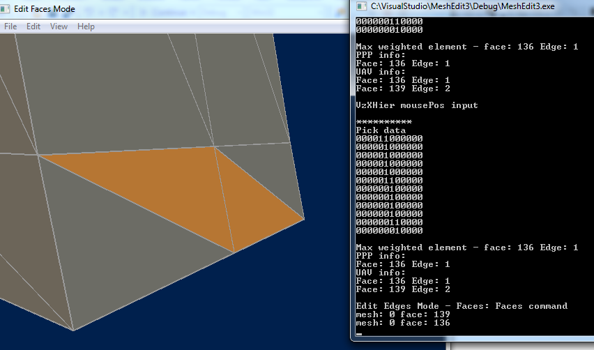
In the above image - the mouse was clicked near the vertical edge in the center of the view. The "Pick data" (on the right) shows diagramatically which pixel positions in the pick rectangle around that mouse position had data written to them. Below that diagram, it is noted that the data in the pixel nearest the pick position was for face 136, edge 1.
A bit further below, note that the UAV data indicates both face 136 - edge 1, and face 139 - edge 2 traversed the pick rectangle. In face selection mode, the triangles on either side of that edge were selected and, as expected, face 136 is on one side of the edge, and face 139 is on the other. That is, face 136-edge 1 was drawn first, edge data was written to the second (PPP) rendertarget and to the UAV. Face 139-edge 2 was later drawn at the same position, but the data written to the PPP target was discarded by depth testing. However, that data was also written to the UAV which persisted.
Although mesh vertex data has to be examined to determine which edges listed in the UAV are coincident with the edge "selected" in the PPP process, there are just a few candidates to test, compared to a more traditional approach which would require testing every edge in the mesh to determine if it's close to the pick position, and compare hits in that search to determine which edges should be considered "selected."

 ): Big memory saving in contrast to having a full resolution ID texture. I currently use it for instance selection and surprisingly the additional branch (I only write to the UAV if the mouse coord matches the pixel exactly) doesn't seem to disturb much. Taking Ashaman73's advice I also use a event query (successfully for the first time) to make the read back not stall: Render, CopyResource (it's only one pixel), issue query, then in a later frame, check the query and map/read if it's done. Nice.