Follow up post to the preivous update. I added the point light and texture compression in my Vulkan miniengine this time 🙂
Two small testing of the features as shown in the video. The point light implementation includes lighting, culling and ray traced shadow.
The texture compression now includes BC1, 3, 4, 5 at the moment. This article is the record of this change.
*Disclaimer: This is just a personal practice of engine programming. Seeking something else if you're for game developing.
Git link: https://github.com/EasyJellySniper/Unheard-Engine
§Point Lights
An important component in video game. Bloody suitable for a bonfire or a lightbulb, point light is the key to acheive these effects.
Rasterization or Computing? A question that graphic programmers would ask themselves when selecting the implementation.
Assuming it's for deferred pass. Using rasterization method isn't that bad. But what if we want to lit in forward pass? Like for translucent stuffs?
Since forward pass needs to evaluate lighting result immediately. Shader usually needs to iterate all point lights in pixel shader.
In that case, the performance spike would be huge! And it can even calculate lighting on a pixel that isn't within any point light range at all…what a waste!
So in UHE, I'm going with computing method. The idea is still to iterate all point lights in calculation. But instead of iterating all, I look up a list and iterate stored point light indices.
And this list is generated in a culling pass.
Tiled Culling Pass
The goal is to check if a pixel is covered by a point light radius. We don't know how many point lights would be on a pixel, so storing both [number of point lights] and their [indices] are necessary.
This can be done with ByteAddressBuffer, which stores integer only. But a buffer can not have dynamic size, the size is determined when it's created. That is, the [max number of point light] needs to be defined.
Consider 1080p, and allows 8 point lights per pixel. The data size is 1920 x 1080 x 9 (plus the first number to tell how many point lights). It's about 17mbs! That's luxury.
Which is why it usually uses a [tile] instead. Assuming tile size is 32 x 32 each, the storage becomes (1920 / 32) x (1080 / 32) x 9, it just needs 17kbs!
The implementation steps:
- Find min/max depth of a tile.
- Construct the tile frustum.
- Sphere-frustum testing.
// calc view space frustum
void CalcFrustumPlanes(uint TileX, uint TileY, float MinZ, float MaxZ, out float4 Plane[6])
{
	// ... Skipped, tile to view position conversion

	// plane order: Left, Right, Bottom, Top, Near, Far
	// note the cross order: top-to-bottom left-to-right
    Plane[0].xyz = normalize(cross(Corners[2], Corners[0]));
    Plane[0].w = 0;

    Plane[1].xyz = -normalize(cross(Corners[3], Corners[1])); // flip so right plane point inside frustum
    Plane[1].w = 0;

    Plane[2].xyz = normalize(cross(Corners[0], Corners[1]));
    Plane[2].w = 0;

    Plane[3].xyz = -normalize(cross(Corners[2], Corners[3])); // flip so top plane point inside frustum
    Plane[3].w = 0;

    Plane[4].xyz = float3(0, 0, 1);
    Plane[4].w = -MinZ;

    Plane[5].xyz = float3(0, 0, -1);
    Plane[5].w = MaxZ;
}

void CullPointLight(uint3 Gid, uint GIndex, float Depth, bool bForTranslucent)
{
    // .... Skipped, finding min/max depth

    float4 TileFrustum[6];
    CalcFrustumPlanes(Gid.x, Gid.y, MaxDepth, MinDepth, TileFrustum);

    for (uint LightIdx = GIndex; LightIdx < UHNumPointLights; LightIdx += UHLIGHTCULLING_TILE * UHLIGHTCULLING_TILE)
    {
        UHPointLight PointLight = UHPointLights[LightIdx];
        float3 PointLightViewPos = WorldToViewPos(PointLight.Position);

        bool bIsOverlapped = SphereIntersectsFrustum(float4(PointLightViewPos, PointLight.Radius), TileFrustum);
        if (bIsOverlapped)
        {
            uint StoreIdx = 0;
            InterlockedAdd(GTilePointLightCount, 1, StoreIdx);

            // discard the result that exceeds the max point light per tile
            if (StoreIdx < UHMaxPointLightPerTile)
            {
                if (!bForTranslucent)
                {
                    OutPointLightList.Store(TileOffset + 4 + StoreIdx * 4, LightIdx);
                }
                else
                {
                    OutPointLightListTrans.Store(TileOffset + 4 + StoreIdx * 4, LightIdx);
                }
            }
        }
    }
    GroupMemoryBarrierWithGroupSync();

	// output final result, the first 4 bytes stores the number of point light per tile
    // then it stores the point light indices that overlapped with this tile
    if (GIndex == 0)
    {
        if (!bForTranslucent)
        {
            OutPointLightList.Store(TileOffset, min(GTilePointLightCount, UHMaxPointLightPerTile));
        }
        else
        {
            OutPointLightListTrans.Store(TileOffset, min(GTilePointLightCount, UHMaxPointLightPerTile));
        }
    }
}
(Referring LightCullingComputeShader.hlsl for full code)
To build a frustum, it needs 4 corner points of a plane, and near/far plane value. The Z value uses for finding corner points shouldn't matter as I'm doing this in the view space.
So either using the point sets at near plane or far plane, I get the same camera-to-corner vector. I chose the corner points at the far plane.
And to test sphere-frustum intersection, I used the implementation in Real-time collision detection, Christer Ericson (2005).
Then, store the indices if it passed intersection. But why for (uint LightIdx = GIndex; LightIdx < UHNumPointLights; LightIdx += UHLIGHTCULLING_TILE * UHLIGHTCULLING_TILE) instead of regular for loop?
This is to utilize the [thread group] of compute shader. Given the dispatch code in my C++ side:
// dispatch light culliong
uint32_t TileCountX, TileCountY;
GetLightCullingTileCount(TileCountX, TileCountY);
GraphBuilder.Dispatch(TileCountX, TileCountY, 1);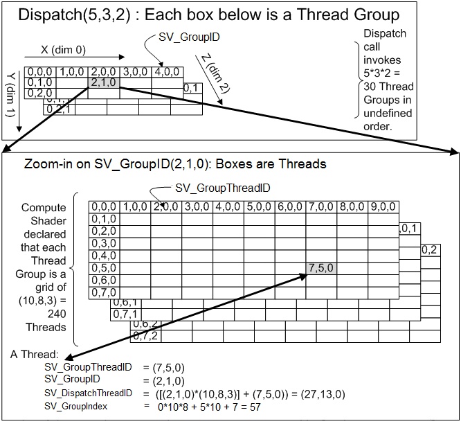
https://learn.microsoft.com/en-us/windows/win32/direct3dhlsl/sv-groupthreadid
Assume my tile size is 32 at 1080p, then the tile count will be 61 x 34 (safely round-up). In the shader main entry, the [numthread()] is set to the tile size. So each group(tile) will have 1024 threads when doing the calculation.
So what's the reason to go with regular for loop? If I just let them do [0…NumOfPointLight] iteration, I'm completely wasting the advantage of compute shader!
That is why InterlockedAdd is used in the loop. Multiple threads are accessing there, operation needs to be done atomically.
But be careful, this also introduces the inconsistency indices order for different tiles that lit by the same set of point lights.
For exmaple, both tile A and tile B are lit by point light 0 - 5, but stored indices could be 0,2,3,1,4 for tile A, and 2,0,4,1,3 for tile B. As we can't control the order of threads.
So when using the culling results, be sure to calculate ALL of them in the list. Since light calculation can be accumulated, it won't be an issue if you don't skip any light. (Thanks to commutative property of addition!)
Performance tips when doing tiled culling:
- Doing at lower resolution. Why not? Just be sure to adjust a proper tile size. I did half resolution of 1440p in the demo video, and got 0.04x ms. Which is decent enough. I've even considered quarter resolution, but that seems too much.
- Lower the max number of point lights of a tile. I find the performance varies when changing this number. I believe higher number causes longer memory access time. For now I set it as 16.
Translucent consideration
Since translucent doesn't output depth in general. To store the list for translucent object, I COULD simply set minimal depth as 0. Then any translucent objects between camera position and deepest object position can receive point lights properly.
But I've mentioned in the previous posts, UHE outputs another translucent depth buffer for other purposes. So I simply sample from the translucent depth and do the same testing.
Receiving Point Light
Using the result of light culling is straight forward and simple:
    uint TileX = DTid.x / UHLIGHTCULLING_TILE / UHLIGHTCULLING_UPSCALE;
    uint TileY = DTid.y / UHLIGHTCULLING_TILE / UHLIGHTCULLING_UPSCALE;
    uint TileIndex = TileX + TileY * UHLightTileCountX;
    uint TileOffset = GetPointLightOffset(TileIndex);
    uint PointLightCount = PointLightList.Load(TileOffset);
    TileOffset += 4;

    float3 WorldToLight;
    float LightAtten;
    float AttenNoise = GetAttenuationNoise(DTid.xy);

    UHLOOP
    for (Ldx = 0; Ldx < PointLightCount; Ldx++)
    {
        uint PointLightIdx = PointLightList.Load(TileOffset);

        UHPointLight PointLight = UHPointLights[PointLightIdx];
        LightInfo.LightColor = PointLight.Color.rgb;

        WorldToLight = WorldPos - PointLight.Position;
        LightInfo.LightDir = normalize(WorldToLight);

		// square distance attenuation, apply attenuation noise to reduce color banding
        LightAtten = 1.0f - saturate(length(WorldToLight) / PointLight.Radius);
        LightAtten *= LightAtten;
        LightAtten += AttenNoise;
        LightInfo.ShadowMask = LightAtten * ShadowMask;

        Result += LightBRDF(LightInfo);
        TileOffset += 4;
    }
Read the number of point lights and then read the index, calculate lighting individually. Very simple. I'm applying a square distance attenuation now.
The attenuation noise is used for reducing the color banding. Anything that based on distance formula has a great chance to have this issue.
Inside the attenuation noise function is a dithering method. Which is based on the On generating random numbers, with help of y= [(a+x)sin(bx)] mod 1 , W.J.J. Rey.

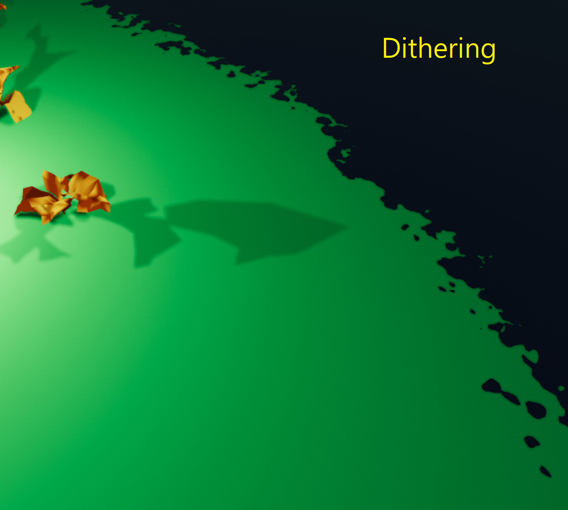
The difference should be obvious.
Ray-Traced Point Light Shadow
Detailed in RayTracingShadow.hlsl.
Again, I read the point light list as well. There is no need to trace all point lights of a pixel. Comparing to directional light, it only needs to change the direction vector (from object to point light) and the TMax (distance from point light to the object).
I've also changed the attenuation model this time. In previous versions, I assume the attenuation is 1.0f at the beginning and blend different shadow strength with min() operation.
But I find that doesn't fit how lighting works in real world. Instead, I set the attenuation as 0.0f intially this time. And if ray fails to hit, add the attenuation by saturated NdotL.
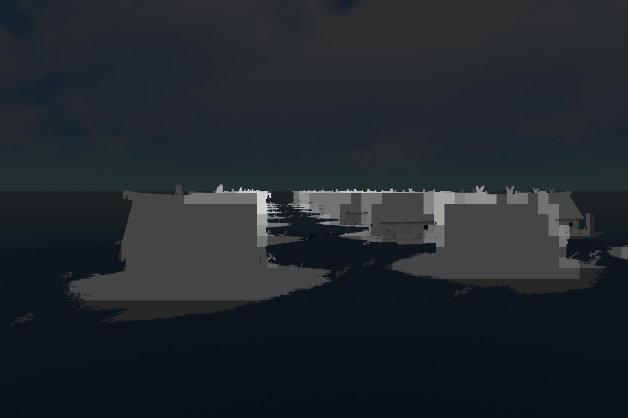
Point light performances
As shown in the test video. There are 54 point lights in the scene at the moment. All of them are ray-traced. Tested at 1440p.
Light culling is around 0.05ms. Light receiving is around 0.05ms as well. (0.2 - 0.3ms without culling)
And RT shadow is around 0.4ms. ( 1+ ms without culling!)
Without video recording, it can be up to 2 ms at some locations. I won't say there isn't any performance hit.
But considering all of them are real time lighting, I think the perf is acceptable at the moment.
§Texture Compression
Another important feature. This not only reduces the storage, but also improves the rendering performance.
Despite the interface is simple, I have an editor to choose compression mode. Which contains BC1, 3, 4, 5 for now. Skipped BC2 as it's a bit embarrassing. I'll add BC6H in the future.
I implemented my own compressor by following the Block Compression document.
- BC1, for RGB. (I don't use this for the alpha.) VK_FORMAT_BC1_RGB_UNORM_BLOCK or VK_FORMAT_BC1_RGB_SRGB_BLOCK.
- BC3, for RGBA. VK_FORMAT_BC3_UNORM_BLOCK or VK_FORMAT_BC3_SRGB_BLOCK.
- BC4, for single channel. VK_FORMAT_BC4_UNORM_BLOCK
- BC5, for two channels. VK_FORMAT_BC5_UNORM_BLOCK
Looks like a lot of works but they're simple. The color part of BC3 uses the same rule as BC1. BC4 and BC5 uses the same rule for every channel as alpha part of BC3.
(Update: I was wrong about BC3, the color part of BC3 will always go with color0 ≤ color1 case and only actually has 3 reference colors! So to store pure color, it could be worse than BC1.)
So there are only two big things for those compression: RGB compression and alpha compression.
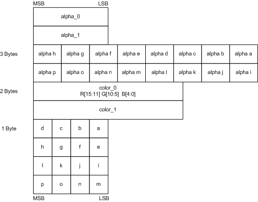
For color, I need to choose two references and interpolate another 2 values. The a to p in a block will store the nearest color index when comparing to 4 reference colors.
Simiarly, I also need to choose two reference alpha and interpolate another 5 values. The alpha a to p in a block will store the nearest alpha index when comparing to 8 reference alphas.
The full compressor code is here. I'll only mention a little part of it. The key point is how to select the best pair of reference color/alpha.
Simply using the min/max color in a 4x4 block won't get a decent result. Imaging a block that consists with Red, White, Black. The reference colors would be (255,255,255), (0,0,0). Their interpolation would completely be gray. And the Red is missing right away!
I need to find a pair of color so that every other colors in the block will have the smallest distance to them. Sounds familar? Yes, it's some how like a linear regression problem.

But I didn't actually implement the solution of linear regrssion. I made it simpler than that.
UHColorBC1 EvaluateBC1(const UHColorRGB BlockColors[16], const UHColorRGB& Color0, const UHColorRGB& Color1, float& OutMinDiff);
UHColorBC3 EvaluateBC3(const uint32_t BlockAlphas[16], const uint32_t& Alpha0, const uint32_t& Alpha1, float& OutMinDiff);
I still tested every pair of colors in a block. But instead, I simply added a output parameter that stores the sum of the minimal difference during a test.
// *********** START inside EvaluateBC1() function
int32_t BitShiftStart = 0;
for (uint32_t Idx = 0; Idx < 16; Idx++)
{
	float MinDiff = std::numeric_limits<float>::max();
	uint32_t ClosestIdx = 0;
	for (uint32_t Jdx = 0; Jdx < 4; Jdx++)
	{
		const float Diff = sqrtf(UHColorRGB::SquareDiff(BlockColors[Idx], RefColor[Jdx]));
		if (Diff < MinDiff)
		{
			MinDiff = Diff;
			ClosestIdx = Jdx;
		}
	}

	OutMinDiff += MinDiff;
	Result.Indices |= ClosestIdx << BitShiftStart;
	BitShiftStart += 2;
}
// *********** END inside EvaluateBC1() function

// *********** START function that calls EvaluateBC1()
float BC1MinDiff = std::numeric_limits<float>::max();
UHColorBC1 FinalResult;
UHColorBC1 Result;
float MinDiff;

for (int32_t Idx = 0; Idx < 16; Idx++)
{
	for (int32_t Jdx = Idx + 1; Idx < 16; Idx++)
	{
		Result = EvaluateBC1(BlockColors, BlockColors[Idx], BlockColors[Jdx], MinDiff);
		if (MinDiff < BC1MinDiff)
		{
			BC1MinDiff = MinDiff;
			FinalResult = Result;
		}
	}
}

// there is a chance that minimal distance method doesn't work the best, use min/max method for such case
Result = EvaluateBC1(BlockColors, MaxColor, MinColor, MinDiff);
if (MinDiff < BC1MinDiff)
{
	FinalResult = Result;
}
// *********** END function that calls EvaluateBC1()
After doing 15x(15+1) / 2 times comparison. I choose the result that has the minimal total distance.
Also comparing with the result that simply uses min/max color in a block, in case the minimal distance method isn't the best.
After compression is done, it's just to create an VkImage based on format and copy the mip data to it. (See Texture2D.cpp for the upload of data)
Result comparison:


Maybe I should actually count the error% for this. But visually, I don't see much difference before/after the compression.
The input is even not that perfect - it's originally a JPG, which is already a lossy compression. I bet it can be better with an uncompressed source!
— The article Ends —