PBR Metalness equation

Started by
16 comments, last by dpadam450 8 years, 5 months ago

All of the equations you've posted are completely wrong.

First, pick a BRDF. Let's say you pick Cook-Torrence for specular. There's 3 parts to it: The specular Distribution function (Blinn-Phong and GGX are common choices), the Fresnel function (Shlick is the common choice) and the Geometry function (Shlick/Smith is a common choice). You also pick Lambert for diffuse.

You end up with: Final colour = Lambert + D*F*G

D is based on roughness. e.g. traditional blinn-phong would use D = pow( dot(N,H), decode(roughness) ) (where maybe decode(x) = pow(2, (1-x)*8192), etc...). This is a scalar variable.

F is based on the reflectivity / metalness. This is a spectral (colour) variable, but for non-metals the colour is almost always grey, so you can optimize it to be scalar in that case.

Schlick's F is F0 + (1-F0)*(1-pow(dot(H,V),5)) -- which is equivalent to: lerp( F0, white, 1-pow(dot(H,V),5) ) -- the lerp version makes it intuitive as to why at grazing angles, metallic reflections become desaturated as well as more intense.

G is then some magic that tries to make it match reality more tongue.png

You're confusing yourself by trying to make this make sense with cubemaps now -- that's IBL, a different topic.

With IBL, say you've got a 256x256 cubemap (x6 faces). That's equivalent to having an array of 393216 directional lights that you want to apply to your object. IBL is the study of how to apply those 400K directional lights extremely cheaply.

The common process is: look very carefully at the math behind D, F & G, and use them to create a very specific convolution (basically: a blurring function!) that mimics their distributions. You then use this specific blurring function to create many blurred (convolved) copies of your cube-maps, for different roughness values, viewing angles, etc. You then compress all this data together into a big look-up-table. There's a nice property that versions of the cupe-map that are baked for high roughness values tend to be extremely blurry, so you can store them with reduced resolution. You take advantage of that and use mip-maps to store an array of increasingly blurring cube-maps.

At runtime, instead of computing D, F & G for hundreds of thousands of directional lights, you feed the BRDF inputs into your look-up-table and fetch the precomputed result.

Common/fast implementations of this idea only perform the blurring based on the D function, and only perform the lookup based on the roughness parameter. This is an approximation of the truth, as you really need to be accounting for the full function, and you need to be looking up based on the roughness and the dot(H,V) value (as this causes stretched reflections, as you see on wet roads). The Unreal 4 and Frostbite PBR papers describe some better approximations that try to improve on this common model.

If you want to use this for diffuse, you can use the same approach to make a specific convolution function for Lambert and precompute your big lookup table containing the results of the "400K lights ? Lambert", but the specific "blurring function" will be different, and you'll end up with a completely different cubemap.
Advertisement

I don't get it then. The equation you posted has been around forever. This is the same thing I've been using for 10 years (except for the G part) unless I missed something big. I thought the whole PBR idea was replacing the actual "point" light with real cubemaps, since light comes from everywhere and surfaces have micro-indents/imperfections etc, that we blur this cubemap down which works as an approximation of light coming and going in random directions.


That's why I'm confused in general. Because the incoming light on a surface is a perfect image. Lots of little normals scatter it. So I thought N*L was being replaced completely because there really isn't 1 normal unless we zoom into a surface pretty much close to the atomic level. So we factor N*L as a blurred environment map. How is that not the case in PBR? This makes logical sense to me.

I think I'm just going to write a shader that makes sense as a modified version of basically what we have been talking about is the same thing just some minor thing I'm not understanding.

But in real physical lighting, and as I understood PBR, there is no actual L vector. There are just photons coming from all directions with different intensities.
I guess I just thought PBR was the defined by that. Everything else you are saying is that, I need to only change 2 variables in the old equations and I have PBR? I've never seen an example of PBR without a cubemap and you are suggesting that is some other topic that isn't needed.

I guess I'm just going to have to fiddle around with some shaders and see what results I get relative to these other PBR viewers.

NBA2K, Madden, Maneater, Killing Floor, Sims http://www.pawlowskipinball.com/pinballeternal

Kind of long, about to sleep. My main point I was getting at with this equation was:

A mirror/metal spoon etc. Pure reflective metal with no surface imperfections, colored or not, will always reflect 100% of the light. At any direction to the surface. Once you approach 90 degrees to the surface, the color of the metal is not present because of the fresnel effect bounding pure light off the surface. And your equations have to break down to what I posted:

Output = 0*red + mix( cubeMap*red, cubeMap, fresnelAmount)

Any colored mirror has to break down to that. Because a bathroom mirror has no tint, it has no fresnel effect because it already reflects everything, and for a bathroom mirror your equation breaks down futher into:
Output = cubeMap

NBA2K, Madden, Maneater, Killing Floor, Sims http://www.pawlowskipinball.com/pinballeternal

The equation you posted has been around forever. This is the same thing I've been using for 10 years (except for the G part) unless I missed something big.

If you're not using the G part, then you're not using Cook Torrence model. Most PBR shaders used by games seem to be Cook-Torrence / or other microfacet models.
Using traditional Blinn-Phong for the D term is not PBR -- I just used it for an example of choosing a BRDF. Traditional Blinn-Phong loses a huge amount of energy on smooth surfaces that it really should be preserving, so it doesn't behave like any real world material.
A PBR BRDF must be energy conserving (never output more than the intputs), must obey Helmholtz reciprocity, and should be able to (almost) reproduce some set of real world sampled BRDF's that have been measured using a gonioreflectometer.
Traditional Blinn-Phong (plus Shlick Fresnel) doesn't fit the bill.
Cook Torrence using Normalized Blinn-Phong (pow(dot(N,H),decode(roughness))*(decode(roughness)+1)/(2*pi)) as the D term (and other sensible functions for the F and G terms) is actually able to almost reproduce real-world BRDF measurements. If you replace that D term with a different one (Beckmann, GGX, etc), then you come closer to matching real world materials. Also, different real-world materials obtain closer reproductions with different D functions.

So PBR is basically - can I reproduce a real-world material with this function. Traditional Blinn-Phong gets a big "no, never". The models in use by current games gets an "almost, sometimes". If you want to see if you can reproduce BRDF measurements and you don't own a gonioreflectometer, you can obtain other people's samples, such as the MERL database.

So I thought N*L was being replaced completely because there really isn't 1 normal unless we zoom into a surface pretty much close to the atomic level.

N·L is still extremely important. The physical meaning of the N·L term is the projection of an incoming light beam onto a 2D surface, to measure the surface area that the incoming energy has been spread over. When N·L approaches zero, the incoming light beam is being spread over an infinitely large area, so it's energy density per area approaches zero.

It's a common misunderstanding that the Lambert diffuse BRDF is "N·L * DiffuseColor" -- when actually it's just "DiffuseColor".
N·L is actually an immutable part of the rendering equation itself, not a part of the BRDF.

Also, you don't have to get to the atomic level for something to become "optically flat", you just have to be smaller than the EM wavelength that you're using. That's a few hundred nanometres for visible light. Optical engineers can actually build 100% "optically flat" objects that behave as a plane as far as visible light is concerned.

Because a bathroom mirror has no tint, it has no fresnel effect because it already reflects everything, and for a bathroom mirror your equation breaks down futher into:
Output = cubeMap

A bathroom mirror is not a perfect mirror. It will have a small amount of roughness and it's F0 value is maybe 97% biggrin.png Also, there's a layer of glass in the middle, so the most direct light rays have an air->glass, glass->silver, silver->glass, glass->air event history -- some outgoing rays will be unlucky and experience internal reflection during the glass->air step, and actually reflect back towards the silver rather than refracting into the air! Accounting for these extra reflection paths will also dim the mirror by a few percent, and create interesting behaviours at glancing angles, as the glass layer approaches 100% reflectivity in that case, greatly complicating things!

Yes, a theoretical perfect mirror has zero roughness and 100% F0, so F/G do nothing, and D is a Dirac delta function (a graph that is zero everywhere, except infinity at one peak). The perfect mirror BRDF isn't very useful though -- it can only represent one theoretical material. At the other extreme is the perfect diffusing material, which is described by the Lambert BRDF. All real materials exist somewhere in the middle.

But in real physical lighting, and as I understood PBR, there is no actual L vector.

If you're evaluating any individual light, there's still an L vector.
When rendering a Lambertian surface, if you're evaluating a spherical light which is above the horizon of your surface, then using an L vector at the centre of the sphere is equivalent to individually integrating photons that are coming from many different L vectors all over the sphere -- much how in astrophysics we don't need to know about each grain, but just the centre of mass.
In any case, each photon still has it's own L vector. In a cube-map (IBL), each pixel has it's own L vector. The brute-force "ground truth" result is to treat every pixel as a small area light source. A correct IBL implementation will match that ground truth.

I've never seen an example of PBR without a cubemap and you are suggesting that is some other topic that isn't needed.

Yes, PBR is the practice of basing all of your equations of real physics, and using real world measurements (And theoretical experiments) to validate your results.
Using cube-maps for lighting is IBL, which is an orthogonal topic. You can use PBR without IBL, and IBL without PBR. Correlation != equality...
However, PBR is viral - you can't just do it do one part of your renderer and be done - every feature must be PBRified.
IBL is very popular right now, so that means that PBR games have to spend the time PBRifying their IBL code.

IBL is a great way to do ambient lighting, so it's also extremely popular these days. However that doesn't mean you don't need analytic (point/spot/directional) lights... If you put the sun into your cubemap, you can't then later on get rid of that sunlight with a shadowmap (without also getting rid of the skylight / ambient bounce light / etc). Most games use IBL for sky and bounced ambient light, and analytic lights for the sun and man-made light sources.
On the PBR trend though is giving physical volume to analytic no lights - point lights become spheres or tubes, spot lights become discs or rectangles, etc... Unreal and Frostbite have published some info on their approaches to PBR area lights.

Also, the mipmapping/blurring approach itself is an approximation used to optimize IBL so that it's feasible to do in realtime. Film renderers won't do this pre-blurring trick as it introduces a lot of small errors.
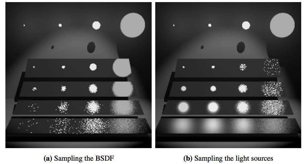
If you want to understand IBL, implement it using brute force Monte Carlo sampling -- generate thousands of random rays for each pixel, sample the cubemap for each ray to measure the incoming radiance, run that through your BRDF and then average all the results together weighted by the probability that the reflection ray would be produced by the microsurface.
For the perfect mirror, thats simple as only one reflection direction has 100% probability and every other direction has 0%.
For other materials, you need to convert the D term (the NDF) into a probability density function.

Here the PBR shader code I use :


float3 Diffuse_Lambert( in float3 DiffuseColor )
{
  return DiffuseColor * ( 1.0f / PI );
}

// [Walter et al. 2007, "Microfacet models for refraction through rough surfaces"].
float D_GGX( in float Roughness, in float NoH )
{
  float m = Roughness * Roughness;
  float m2 = m * m;
  float d = ( NoH * m2 - NoH ) * NoH + 1.0f;
  return m2 / ( PI * d * d );
}

// [Schlick 1994, "An Inexpensive BRDF Model for Physically-Based Rendering"].
float SchlickFunc( in float v, in float k )
{
  return 1.0f / ( v * ( 1.0f - k ) + k );
}

// [Schlick 1994, "An Inexpensive BRDF Model for Physically-Based Rendering"].
float Vis_Schlick( in float Roughness, in float NoV, in float NoL )
{
  float k = ( Roughness * Roughness ) * 0.5f;
  return SchlickFunc( NoL, k ) * SchlickFunc( NoV, k );
}

// [Schlick 1994, "An Inexpensive BRDF Model for Physically-Based Rendering"]
// [Lagarde 2012, "Spherical Gaussian approximation for Blinn-Phong, Phong and Fresnel"]
float3 F_Schlick( in float3 SpecularColor, in float VoH )
{
  float Fc = pow( 1.0f - VoH, 5.0f );
  return saturate( 50.0f * SpecularColor.g ) * Fc + ( 1.0f - Fc ) * SpecularColor;
}

float3 ComputeSpecFactor( in SURFACE_DATA SurfaceData, in float3 LightDirection, in float NdotL )
{
  // Variables used to compute the lighting factor.
  float3 ViewDirection = normalize( -SurfaceData.Position );
  float3 HalfDirection = normalize( LightDirection + ViewDirection );
  
  // Compute the lighting factors.
  float NdotH = max( 0.0f, dot( SurfaceData.Normal, HalfDirection ) );
  float NdotV = max( 0.0f, dot( SurfaceData.Normal, ViewDirection ) );
  float VdotH = max( 0.0f, dot( ViewDirection, HalfDirection ) );
  
  // Generalized microfacet specular.
  float D = D_GGX( SurfaceData.Roughness, NdotH );
  float Vis = Vis_Schlick( SurfaceData.Roughness, NdotV, NdotL );
  float3 F = F_Schlick( SurfaceData.SpecularColor, VdotH );
  
  // Return the specular factor.
  return D * Vis * F;
}

I'm close but I don't get how F0 = a color. Fresnel is a scalar I thought? An amount of reflectivness given a direction of the viewer to the surface. So how do I plug a color in to the fresnel equation?


"Fresnel is a scalar.." Not really. Fresnel is a "complex" function (as in complex number : two scalar components),
one scalar function for orthogonal component and one scalar function for the parallel component of light
(light is a wave in a 3D space). It is a function, not a single number, because materials have very different reaction
to light based on its wavelength. Some materials will reflect some wavelength more than an other.

So when you describe F0 as a color with three scalar channels, you already simplified the problem a lot smile.png.

The reason why metals who should be entirely reflective on all wavelengths are not is because of the underlying physics
(it takes different amounts of energy to move electrons in their lattice of atoms).
This is where Gold or Copper get their color. Also some other metals get their colors because of
destructive interference (some thin oxidation layer for example at the surface, or metal plating, and so on).
Some will have a color coating (paint, and so on).

I thought the whole PBR idea was replacing the actual "point" light with real cubemaps,
since light comes from everywhere and surfaces have micro-indents/imperfections etc, that we
blur this cubemap down which works as an approximation of light coming and going in random directions.


Not really.. Also the idea behind PBR is NOT to compare your output to another PBR renderer,
but go back to first principles of light. Of course (almost) nobody does that and everybody is using the same biased
equations as a (or several) seminal paper happy.png.

Anyway : cubemaps and (apparent) point lights are two approximations of the underlying physics on the opposite end of
a spectrum.
One work well for some light sources and the other one work better with other light sources. It's the trade offs
you have to do to achieve your real time performance (even offline renderers have limits !).

Basically you want to avoid a solution that is too generic as to prevent you to do useful approximations. Which is why
it is useful to segregate light sources into different types. In PBR, the idea is that you make informed approximations instead of ad-hoc ones. But you still make them.
(And ideally you'd have also figured where those approximations break down).

That's why I'm confused in general. Because the incoming light on a surface is a perfect image.
Lots of little normals scatter it. So I thought N*L was being replaced completely
because there really isn't 1 normal unless we zoom into a surface pretty much close to the atomic level.
So we factor N*L as a blurred environment map.
How is that not the case in PBR? This makes logical sense to me.


Lighting equations have the form of integrals (A big sum over a continuous range). The summed terms are usually much
simpler and yes we still use the notion of a normal and incident light (in the microfacet model or the BRDF model).

The (pre-)blurred environment map is used as a quicker implementation that may or may not be accurate
depending on the situation.

But in real physical lighting, and as I understood PBR, there is no actual L vector.


There is a light direction inside the integrals. (we sum over all possible incoming light directions).

But since it's impractical to sum that integral in real time you try to pre-sum as much as possible and yes sometimes you get
an estimated pseudo-"light direction" that may or may not accurately reflect how the light
really interacts with the material.

I've never seen an example of PBR without a cubemap and you are suggesting that is some
other topic that isn't needed.


You have to be careful to not have your perceptions tinted by your limited experience.

Anyway cubemaps are a useful tool in real time rendering so yes they're used often.

Any colored mirror has to break down to that. Because a bathroom mirror has no tint,
it has no fresnel effect because it already reflects everything, and for a bathroom mirror
your equation breaks down futher into:
Output = cubeMap


The point is : if your material is already perfectly fine with a simpler model, then there is no need
to make it more complex than that. BUT 1- very few materials act as perfect mirrors,
so that insight will be useful for a very small fraction of your scene. 2- In theory you could go back
to the first principles and re-derive the effect of electrons of the glass and metal on the photons to find out why your
mirror material is fine as it is. This is probably not needed in your case but you could if you were so inclined
(and I'm sure there are physicists out there who HAVE to do that in order to create better mirrors for specific applications).

Addenda : If the idea of separate approximations is strange to you here's an illustration (for an offline renderer) :

veach.jpg

You can see that based on the dimension of the light and the type of surface (roughness) the sweet spot in term of artifacts will be at a very different place. So the whole idea that you have to solve is how to try to be generic (to accommodate different environments), but not as generic that you miss the sweet spot for two common categories of lighting+material combinations. In real time it often means you'll have to keep some approximations separate (for example low frequency ambient vs bright quasi-punctual light).

I use a value of 0.08 as multiplier of the specular value, 0.03 is more correct ?


SurfaceData.DiffuseColor = Diffuse_Lambert( FinalBaseColor.rgb - ( FinalBaseColor.rgb * Metallic ) );
SurfaceData.SpecularColor = lerp( 0.08f * Specular, FinalBaseColor.rgb, Metallic );

0.03 is a common value to match response to measured materials, but it varies. A common hack is instead of using the entire 8bit range to store "metaless" as hodgeman pointed out, you use the upper range to instead raise f0, up to say 0.18 or 0.16 so you can get gemstone like effects. You can also, if you really want, use the lower range as well. 0 metalness could be 0.02, the slowly raise to 0.03 or whatever value you want as it goes up.

You lose precision, but you don't really need 8bit precision for "metalness" anyway. And it allows a larger range of materials without increasing bandwidth.

I'm an observationalist/artist more than a mathemetician. I never knew what F0 was I just observed that the fresnel effect at a 0 degree angle to a surface was more brighter than just a raw dot product with a reflectance vector and the eye vector. Anyway, my actual shader I "artistically" came up with was exactly adding +.03 to the other part of the fresnel equation. So that was interesting in actually going back to my shaders to find .03 in there.

NBA2K, Madden, Maneater, Killing Floor, Sims http://www.pawlowskipinball.com/pinballeternal

This topic is closed to new replies.

Advertisement