Find the bounds of isometric image

Started by
9 comments, last by frob 6 years, 9 months ago

Has anyone tried finding isometric bounds programatically?

What I'm trying to achieve is to use the Cartesian width and height of the object to find it's isometric bounds, but I think that just doesn't work once the image gets complicated.

The attachments should explain clearly what I'm trying to achieve (note: the bounds drawing isn't perfect).

iso-003.PNG

iso-004.png

iso-005.png

Advertisement

I don't immediately see how you can compute the yellow rectangle. In the drawing, you are using information gleaned from looking at the contents of the image (this part is just a tall part of the building, it's not at ground level. Thus, I will ignore this part of the image when creating the yellow rectangle).

Unless you have a separate image/channel with additional data ("height" or similar?), I don't see how this can be done?

Hello to all my stalkers.

Unfortunately I don't have additional data on this image, actually there are 100s of similar images, I could manually set their bounds, but that would take quite some time, also I think it would be fun to find (if any) way to find the bounding.

I'm thinking we could find the exact bonds of this image from it's pixel data and then guide it using isometric axis (in case there are complicated shape), just trying to come up with a conceptual idea currently, unsure how possible it is to solve this problem.


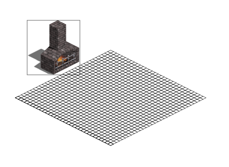
The issue with trying to extract that information from an image is that you have to somehow inform the algorithm of which parts of the image actually affect the footprint. The algorithm can't look at your example image and know that the tall part is a chimney; for all it knows, the tall part lays on the ground and thus affects the footprint, making the object occupy much more area on the back-side of the object where the chimney occludes, even though that area should be open and not affected by the footprint.


When I was still working on isometric games, I always just did the bounds/occlusion/footprint calculation step directly from the geometry in the 3D file from which I rendered the object sprite. The 3D file contains all the information to determine exactly what the footprint of the object is. In the absence of the original 3D file, then you'll probably have to go with a more brute-force approach.


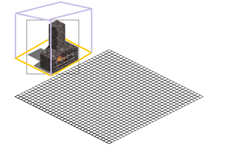
You could probably ease this a bit by building some sort of tool that will allow you to associate a particular object with a rough shape. ie, you could say "this image is LIKE a cube of size XYZ", and build the footprint data from that rough shape. Provide some sort of "grammar" or tool to aggregate simple primitives for more complex shapes. ie, "this image is like a cube of size XYZ plus a box of size WUV located at MNO offset from original shape", etc... How you build this tool or grammar is entirely up to you, but ideally it would:

1) Not take as long to develop as manually determining the footprint of each image would take

2) Allow enough conciseness as to actually reduce the workload of creating each footprint, enough that the overall time savings offsets the time spent developing the tool.


Give that you could iterate on such a tool for quite some time, there would need to be a LOT of images needing done to make it worthwhile.

I see, I guess I would have to develop an adaptive algorithm and train it with lots and lots of data...

4 hours ago, dud3 said:

I see, I guess I would have to develop an adaptive algorithm and train it with lots and lots of data...

I don't know that you'd need to go that far. I mean, yeah, if your main focus were on the tool to do this, rather than on getting a specific task done, then sure.... Spend a bunch of time on it. But writing some kind of advanced algorithm and training it with data sets... no, I don't think that would be a good use of your time if all you need to do is a few hundred sprites for a single game. That would almost certainly take longer than doing them all manually.

My first thought would be to write a simple tool that, when executed in a given directory, would automatically iterate through each isometric sprite in the folder. It would open each sprite in turn, display it on screen overlaid on top of an annotated grid perhaps, then it would wait for my input. It seems like all you are doing is trying to determine a bounding box (rather than a more complex footprint that adheres to the shape of the sprite) so I would have it accept an input string where you key in the dimensions of the box as you perceive it from looking at the grid. Your brain could do the processing, and all you'd have to do is key in a sequence of numbers. It would use your input to write a bounding volume in a file corresponding to the sprite file, and move on to the next.

It would be an extremely simple, brain-dead tool, but even with such a simple tool it's amazing how fast you could churn through several hundred sprites. A couple hours to write the tool, a couple hours to work your way through the sprites, and done. You don't have to spend very much time polishing the tool (odds are you won't use it again down the road, unless you do a sequel or something, and even then you can just try to prepare better by obtaining this information from the artist, or stipulating that the 3D files be provided so you can calculate it).

It seems to me a problem related to the convex hull. There are several algorithms you can find easily on the Web.

One way to find your 2D bounding boxes could be to consider your object as a king of polygon, compute the convex hull, and then get the bounding box.

1 hour ago, JTippetts said:

I don't know that you'd need to go that far. I mean, yeah, if your main focus were on the tool to do this, rather than on getting a specific task done, then sure.... Spend a bunch of time on it. But writing some kind of advanced algorithm and training it with data sets...

Yes that's a great idea, indeed implementing the adaptive algorithm would take more time than 4-5 hours.

I'll fix the issue the way you suggested, and then try writing the adaptive algorithm just as a training for myself.

Thanks.

23 hours ago, yahiko00 said:

It seems to me a problem related to the convex hull. There are several algorithms you can find easily on the Web.

One way to find your 2D bounding boxes could be to consider your object as a king of polygon, compute the convex hull, and then get the bounding box.

Sounds like a nice idea, I'd just have to find the vertices and then the convex hull, I wanted something alike the bounding box on my images, but I think your idea could solve my problem as well.

On 7/7/2017 at 4:07 PM, JTippetts said:

My first thought would be to write a simple tool that, when executed in a given directory, would automatically iterate through each isometric sprite in the folder. It would open each sprite in turn, display it on screen overlaid on top of an annotated grid perhaps, then it would wait for my input. It seems like all you are doing is trying to determine a bounding box (rather than a more complex footprint that adheres to the shape of the sprite) so I would have it accept an input string where you key in the dimensions of the box as you perceive it from looking at the grid. Your brain could do the processing, and all you'd have to do is key in a sequence of numbers. It would use your input to write a bounding volume in a file corresponding to the sprite file, and move on to the next.

This was my first thought as well.

Assuming they're all implemented at the same angles, perhaps they're all 1:2:1, then I second the idea of a tool that generates the bounding boxes with manual adjustment.

With a 1:2:1 image you already know the angles, so you can scan across the images to find the bounding boxes. If you've got a regular grid (perhaps you know they are 4:8:4) you are following then it can be even easier, scan for non-empty cells.  When you hit the first angled-row or angled-column that isn't empty, that's your border. Find near, far, right, and left.

After the automatic bounding box is generated, you'll only need to move the two box lines on the back to capture where the ground ends.  You might be able to estimate that based on the vertical lines, but that might not always be possible.  Either way, you can manually move the rows easily enough.

This topic is closed to new replies.

Advertisement